Table of Contents
Advertisement
Quick Links
Advertisement
Table of Contents

Related Manuals for Imation RDX A8


Summary of Contents for Imation RDX A8
- Page 1 ® User and Service Guide Version 1.0...
- Page 2 © Copyright 2011 by Imation. All rights reserved. This item and the information contained herein are the property of Imation. No part of this document may be reproduced, transmitted, transcribed, stored in a retrieval system, or translated into any language or computer language in any form or by any means, electronic, mechanical, magnetic, optical, manual, or otherwise, without the express written consent of Imation.
-
Page 3: Introduction
This warranty does not apply to normal wear or damage from misuse, abuse or accident. Imation will not be liable for any lost data or other indirect, incidental or consequential damages. This warranty gives you specific rights – you may have other rights that vary from country to country. -
Page 4: Table Of Contents
OCP Navigation ............................20 iSCSI Connection ............................21 i. General Set up of the iSCSI Initiator ....................21 e. Introduction to the RDX A8 Manager ...................... 23 i. RDX A8 Manager Flow Chart ......................23 f. Login Procedures ............................. 24 i. - Page 5 Removing a cooling fan ........................63 ii. Installing a cooling fan .......................... 63 3. Glossary ..................................64 4. List of figures ................................66 5. List of tables ................................67 Index ................................... 68 RDX A8 User and Service Guide — Version 1.0...
-
Page 6: Product Overview
It may be utilized as a table top unit or rack mounted in a 2U high space with the included rack mounting ears. The RDX A8 connects to the user’s computer network via one 1 GB/sec network port using iSCSI protocol. -
Page 7: Operation Modes
(media changer) containing one tape drive. Note that the RDX A8 unit is emulating the LTO tape format to the host application including the actual file format recorded on the RDX cartridge. RDX cartridges which are recorded in this mode are not write/read interchangeable with standard RDX docks. -
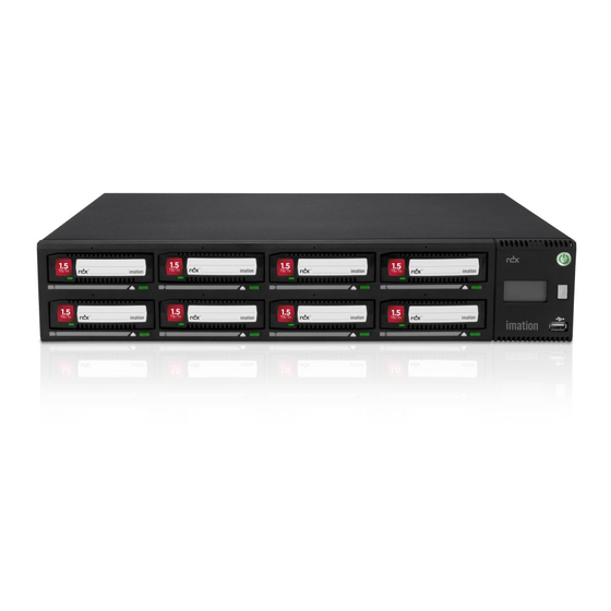
Page 8: Front Panel
Front panel The front panel of the RDX A8 is constructed of durable plastic and is designed to provide both visual appeal and protection from entry of dust/dirt. The eight spring-loaded cartridge bay doors prevent entry of dust when no cartridge is inserted, protect the unit from ESD, and control the cooling airflow through the device. -
Page 9: Led Behavior
LED Behavior 1. Power button LED State Status Description No AC Power is present at the RDX A8 No power rear connector. Unit is in the process of becoming ready Blinking green Unit staring for operation. Steady green Power on Unit is ready for operation. -
Page 10: Rear Panel
Rear panel The rear panel of the RDX A8 provides access to the power connector, ethernet ports, power supply and cooling fan. i. Rear panel layout Figure 2—Rear panel Number Description IEC Power connector -- AC Power connection Power supply CRU... -
Page 11: Ethernet Port Led Behavior
Off – indicates no link is established Speed LED: Amber on – indicates a Gigabit connection (1000 Mbps). Green on – indicates a 100-Mbps connection. Off – indicates a 10-Mbps connection. Table 3—Ethernet port RDX A8 User and Service Guide — Version 1.0... -
Page 12: Product Installation
Horizontal only-either sitting on a table top or mounted in a 19” equipment rack via the included rack mount ears. The RDX A8 weighs 15.7 lbs (7.1 kg) when fully populated with cartridges and must be placed on or mounted... -
Page 13: Installation Precautions
Unpacking the unit Before unpacking the unit, clear a work surface to unpack the RDX A8. Select either a table top location or if the unit is to be rack mounted an open rack location at least 2U spaces in vertical height. -
Page 14: Identifying The Product Components
• Power cord (region dependent) • Printed Quick Start Guide • RDX cartridges Confirm that you received the following in the RDX A8 box: • RDX A8 unit • Rack mounting ears with included mounting hardware • Torx driver for installing rack mounting ears Required additional equipment for a successful installation: •... -
Page 15: Installing In A Rack
5. Secure the unit to the rack using a #3 Phillips screwdriver or your fingers to tighten the two captive thumb screw(s) on each side of the unit. Figure 5—Securing the unit to the rack RDX A8 User and Service Guide — Version 1.0... -
Page 16: Installing Cables And Connections
Rear panel. 1. Inset the Ethernet cable into the Ethernet port #1 of the unit. When the plug is in the full seated position, a positive click should be heard. RDX A8 User and Service Guide — Version 1.0... -
Page 17: Powering Up And Powering Down The Unit
Before powering up the system insure that the network cable connection to the host system is plugged into the RDX A8 Ethernet port 1 -- the right hand port when looking directly at the rear of the unit. A live network connection is necessary to insure the unit receives an IP address from the host network DHCP server or is assigned a static IP address if DHCP services are unavailable. -
Page 18: Product Configuration
OCP – Operator Control Panel The RDX A8 unit includes an LCD based display located on the right side of the unit’s front bezel – referred to as the Operator Control Panel or OCP. Highlights of the OCP are: •... -
Page 19: Ocp Display Content
OCP Display Content Once the RDX A8 unit completes the power up boot sequence the OCP will become active. The OCP will display the system information screen which identifies the unit’s IQN name, current IP address / status of Ethernet port 1, as well as the unit current firmware revision level. -
Page 20: Ocp Icons
OCP Icons The RDX A8 makes use of graphic icons to indicate some conditions to the user. These icons are used both on the local OCP display and in the Active System Graphic in the RDX A8 Manager. The RDX A8 icons in use are shown in the figure below. -
Page 21: Iscsi Connection
For other Microsoft operating systems you may search the Microsoft Web site for the Microsoft iSCSI Initiator. i. General Set up of the iSCSI Initiator The following procedure is used to set up the RDX A8 as a iSCSI Target. 1. Open Microsoft iSCSI Initiator 2. On the “Discovery” tab and under “Target Portals”... - Page 22 8. The IQN for the RDX A8 unit should be shown under available targets. 9. Highlight the RDX A8 IQN by clicking on it. 10. Depending upon which version of MS Initiator in use you may need to either click “Log On”...
-
Page 23: Introduction To The Rdx A8 Manager
The RDX A8 unit uses the web based RDX A8 Manager to allow the user to configure and monitor the unit. The RDX A8 IP address may be viewed in the OCP and is displayed between the cartridge monitoring pages for slot 8 and slot 1 (#1 out of 9 screens in continuous rotation). Once the RDX A8 IP address is known, browse to the unit with your web browser application by entering the RDX A8 IP address in your browser address bar. -
Page 24: Login Procedures
Access the RDX A8 Manager remote management interface via a web browser. Using the IP address visible on the unit’s front panel OCP, enter the IP address into your browser address bar and navigate to the RDX A8 Login page. -
Page 25: Rdx A8 User Access Levels
• The RDX A8 Manager grants the Administrator and Service levels full access to device set up, diagnostics, and logging. • The RDX A8 Manager grants the User level only the ability to monitor device and cartridge status. ii. RDX A8 User Access levels... -
Page 26: Rdx A8 Manager
Status” tab. An overview of the main graphic elements is displayed below. The main navigation is performed via selection (via mouse click) of the Main Topic Bar (element 1 in the RDX A8 Manager page chart) and then selection of the associated Sub Topics (element 2). Key elements are the Active System Graphic (element 7) and the System Information Block (element 3) which are visible on all RDX A8 Manager pages. -
Page 27: Rdx A8 Manager System Information Block
System Date & Time: The current system date and time is displayed. System Mode: This field displays the current RDX A8 system operating mode. IP Address (for Ethernet port 1): The current port IP address is displayed in this field. -
Page 28: Monitoring Cartridge And Device Status - The Monitor Tab
Monitoring cartridge and device status – The MONITOR tab The RDX A8 unit user home page is the “MONITOR” tab for all account logins. Following is a brief description of each function. i. Cartridge Status page Slot #: This field shows the row heading indicating the slot number. -
Page 29: Cartridge Identity Page
This field displays the cartridge label. Note that this label field will always display the default cartridge label when the RDX A8 system is operated in JBOD mode. When the RDX A8 system is operated in Tape Library mode, Tape formatted RDX cartridges will display either the default cartridge label or the user assigned custom label. -
Page 30: Device Status Page
This field displays the power supply status -- Power Good or Power Error. The Power Supply Status will be set to Power Error if any of the monitored voltages fall below or exceed normal operating parameters. Figure 15—RDX A8 Manager Monitor Device Status RDX A8 User and Service Guide — Version 1.0... -
Page 31: Device Identity Page
Device Identity page Vendor ID: This field shows the manufacturer of the RDX A8 device. Product ID: This field shows the product name. Serial Number: This field shows the master serial number of the unit. Firmware Version: This field shows the current firmware revision level and firmware checksum. -
Page 32: User Operations - The Configure Tab
The CONFIGURE tab is available to users with access level of Administrator or Service. i. Device - Set Operating Mode The Device page allows the user to configure the operating mode of the RDX A8, as well as the System Name and the Global Cartridge Lock status. - Page 33 RDX A8 system. JBOD mode JBOD mode allows the RDX A8 to appear to the host operating system as 8 individual storage drives -- each with their own drive letter. Tape Library mode The RDX A8 tape library mode allows data to be recorded to sequentially to RDX cartridges like traditional backup tape devices.
-
Page 34: Cartridge - Labeling Tape Format Cartridges
Cartridge - Labeling tape format cartridges If the RDX A8 system will be operated as a tape library and the user has already created tape format cartridges they may optionally decide to assign custom labels. Custom RDX cartridge labeling may be created under the “CONFIGURE/Cartridge”... -
Page 35: Network Settings
Current selection option, and default choice, is IPV4. Method: The Method will select the IP addressing mode the RDX A8 will use. The two options are DHCP or Manual. The RDX A8 default configuration is DHCP. • DHCP – the RDX A8 will seek out the DHCP-sever on your network and automatically obtain an IP address from the server each time it powers up. - Page 36 Figure 20—RDX A8 Manager Configure Host Name Host Name: Enter the name you wish to use to address this RDX A8. It is recommended that you use a name that is relevant to its location and or its purpose. Domain Name: Enter the name of the domain or workgroup for the attached network.
-
Page 37: Iscsi Settings
Overwrite IQN: Click this check box will allow the user to assign a unique IQN name to the RDX A8 unit. An IQN may be up to 255 characters long. To apply a new IQN name to the device the Overwrite IQN box is checked, the desired IQN is programmed in the IQN field, and the submit button is pressed to apply changes. - Page 38 If this option is enabled the RDX A8 will register its resources with a central iSNS-server. To enable iSNS on the RDX A8, click the check box “Enable iSNS” and enter the IP address for the iSNS-Server in the “iSNS Server” field.
- Page 39 When CHAP is enabled, the initiator must send the correct “Username” and “Target Secret” to gain access to the RDX A8. The “Initiator Secret” field is provided to allow iSCSI mutual CHAP. If mutual CHAP is selected on the Initiator, the RDX A8 will authenticate itself with the initiator using the supplied Initiator Secret.
-
Page 40: User Settings
Assign access rights to the account as follows. User level: User level access only allows access to the “MONITOR” functions of the RDX A8 Manager. The user cannot change any configuration settings/add user accounts/ or reformat/create tape format cartridges. Administrator level: Administrator level grants access to all functions within the unit including “MONITOR”,... -
Page 41: Date And Time Settings
Clicking the “Now” button will synchronize the RDX A8 system time with the time of the computer accessing the RDX A8 Manager. Save the changes to the date and time by clicking the “Submit” button. -
Page 42: Notification Settings
Notification settings E-Mail Notification allows the user to configure the RDX A8 to send email to a selected account upon an identified level of system event. The Notification tab has the following fields: Enable E-mail notification: This check box will enable The Email Notification action, and will allow the user to configure the email parameters. - Page 43 Check if sender authentication is required Username: Enter the authorized user account name for connecting to the selected SMTP server. Password: Enter the authorized user password for connecting to the selected SMTP server. RDX A8 User and Service Guide — Version 1.0...
-
Page 44: Save/Restore Configuration
Settings may be stored to a location on the RDX A8 Manager host computer via selecting the Save configuration button, downloading the file and using the browser pop up to select a storage location via the “Save as” function. - Page 45 Reset configuration may also be accomplished by using a paper clip and depressing the “Hard reset port” switch for 3 seconds then releasing. See Page 10 for location of the hard reset switch on the rear panel of the unit. RDX A8 User and Service Guide — Version 1.0...
-
Page 46: Managing The Unit - The Manage-Tab
Also, selecting any other cartridge from the storage slot side and choosing the load button will result in the automatic unload of the cartridge in the drive. The RDX A8 will only store cartridges back into their original storage slot location (it is not possible to ‘move” cartridges to a different storage slot. -
Page 47: Ejecting Cartridges
Ejecting cartridges Depending on the RDX A8 System Mode, and current activitiy, cartridges may be ejected on the MANAGE/Eject Cartridge screen. The cartridge is ejected by selecting the appropriate slot from the drop down menu and clicking the Eject button. -
Page 48: Initializing Cartridges
Initializing cartridges The RDX A8 uses a specially format on the RDX cartridges to support emulation of tape. In order to apply this special format the user performs a “pre-format” operation via the initialize cartridge function. This cartridge formatting operation is only necessary to perform once and it is suggested the user prepare all cartridges which will be used in the media pool at one time. - Page 49 Re-formatting tape format RDX cartridges back to standard RDX disk To convert previously tape formatted RDX cartridges back into standard RDX disk format the RDX A8 system must be configured in Tape Library mode. The user then selects the “MANAGE/Initialize Cartridge - Disk”...
-
Page 50: Performing Diagnostic Operations - The Diagnostics Tab
Performing Diagnostic operations - The DIAGNOSTICS tab i. Device Logs The RDX A8 unit supports a built in event logging feature designed to facilitate monitoring and trouble shooting of the device. The logs are available for viewing under the “DIAGNOSTICS/Device Logs” tab. -
Page 51: Perform Diagnostics
OCP navigation button and observe the display through various states to confirm operation. Fan Test: It tests the operation of the RDX A8 cooling fan, steps the fan speed through four RPM ranges while monitoring fan rpm. Cartridge Access Test: It tests the operation of each slot location by checking communication with a test cartridge. - Page 52 LED behavior. The LED will blink three times green then three times amber. Note that when the RDX A8 is in the slot UI test mode any inserted cartridge will not be ejected by the associated button push during the test. Once all eight positions have been verified confirm completion of a successful test by selecting “Test Passed”...
- Page 53 To execute the Fan Test select the “Start Test” button. The fan will cycle through four operation speeds while monitoring the fan RPM for the correct reference value. Once the fan test has completed the RDX A8 will report a pass/fail status and the user may click the “OK” button to log the result.
- Page 54 The operator will be instructed to place the user data cartridges back into the unit, and the unit will reconnect to the iSCSI network. Figure 34—RDX A8 Manager Diagnostics Results RDX A8 User and Service Guide — Version 1.0...
-
Page 55: Upgrade Firmware
RDX A8 Manager, then select the “Upgrade” button. The unit will proceed with the upgrade and reboot after the new code is installed. It will be necessary to log back into the RDX A8 Manager to regain access to the management interface. -
Page 56: Reboot
The RDX A8 may be rebooted remotely via the “DIAGNOSTICS/Reboot” tab selecting the “Reboot” tab and clicking the “Reboot” button. Rebooting the unit takes approximately 2 minutes and will require the user to log in to the RDX A8 Manager again after the reboot process is complete. Figure 36—RDX A8 Manager Reboot System... -
Page 57: Rdx Cartridges
4. RDX cartridges This section describes the use of the RDX cartridge in the RDX A8. The RDX cartridge utilizes a removable 2.5” mobile HDD to offer the reliability and performance of disk technology along with the manageability of removable media. -
Page 58: Inserting Cartridges
Figure 39—Inserting cartridges c. Ejecting cartridges The RDX A8 unit has three methods to eject cartridges: - Front Panel Cartridge Eject button - Eject via RDX A8 Manager web interface - Manually eject cartridge via Emergency Eject Port ... - Page 59 (90 degrees) in both the horizontal and vertical planes) pushing in toward the front bezel. Avoid applying force to the emergency eject port in any other direction or damage may occur. RDX A8 User and Service Guide — Version 1.0...
-
Page 60: Appendix
• Efficiency: >85% (Certification 80 PLUS Bronze) • Input power <1,0 W with 10mA output load • Hold up time >15 msec • EMI class A • MTBF > 250 k hours RDX A8 User and Service Guide — Version 1.0... -
Page 61: Regulatory Requirements
(Requires tests according to the actual versions of: – IEC 61000-4-2 – IEC 61000-4-3 – IEC 61000-4-4 – IEC 61000-4-5 – IEC 61000-4-6 – IEC 61000-4-8 – IEC 61000-4-11 (Limits acc. to EN 55024:1998) ) RDX A8 User and Service Guide — Version 1.0... -
Page 62: Cru Replacement
Installing a power supply 1. Locate the power supply bay on left side on the rear panel of the RDX A8 unit, shown in section Rear panel layout, Page 10. 2. Before installing the power supply, inspect the connectors on the power supply. Ensure that the connectors are intact, free of any foreign objects, and have no cracks or deformed or bent contacts. -
Page 63: Cooling Fan
Installing a cooling fan 1. Locate the cooling fan bay on the middle of the rear panel of the RDX A8 unit, shown in section Rear panel layout, Page 10. 2. Before installing the cooling fan, inspect the connectors on the cooling fan CRU and the mating connector in the RDX A8 unit. -
Page 64: Glossary
Refers either to a HDD unit or the direct block addressing scheme used to store and retrieve digital data on the HDD. When the RDX A8 unit is in disk mode direct block addressing is used to access the contained RDX media. - Page 65 Universal Serial Bus is an interface designed to provide high speed connection of various device types in a hot pluggable manner. The RDX A8 system has one USB 2.0 port located on the front panel for various operations (firmware version dependent)
-
Page 66: List Of Figures
Cartridge overview ..........................57 Figure 38 Write-protecting cartridges .........................57 Figure 39 Inserting cartridges ..........................58 Figure 40 Ejecting cartridges ..........................58 Figure 41 Installing a power supply ........................62 Figure 42 Installing a cooling fan ...........................63 RDX A8 User and Service Guide — Version 1.0... -
Page 67: List Of Tables
5. List of tables Table 1 Front panel ..............................8 Table 2 Rear panel ..............................10 Table 3 Ethernet port ...............................11 RDX A8 User and Service Guide — Version 1.0... -
Page 68: Index
Upgrade Firmware ..............55 Operation modes ..............7 Power button ................9 Product Components ..............14 Features ................6 Installation ............... 12 Overview ................6 Warranty caution............3 Product configuration ............18 6395xxxx-A RDX A8 User and Service Guide — Version 1.0...
Need help?
Do you have a question about the RDX A8 and is the answer not in the manual?
Questions and answers