Table of Contents
Advertisement
Quick Links
(1) T100 Control plus
(2) or (3) AT or 3T
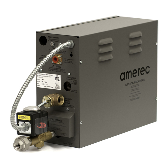
Steam generators
AMEREC STEAMBATH GENERATOR SYSTEMS
FOR USE WITH SYSTEMS INCORPORATING
ONE AT OR 3T "MASTER" STEAM GENERATOR AND
ONE OR TWO AT OR 3T "SLAVED" GENERATOR(S)
STANDARD MODELS CONSIST OF
AT17 = AT 10 + AT7 + T100 CONTROL KIT
AT20 = AT 10 + AT10 + T100 CONTROL KIT
AT30 = AT 10 + (2) AT10s + T100 CONTROL KIT
3T20 = 3T 10 + 3T10 + T100 CONTROL KIT
3T24 = 3T 12 + 3T12 + T100 CONTROL KIT
3T28 = 3T 14 + 3T14 + T100 CONTROL KIT
3T36 = 3T 12 + (2) 3T10 + T100 CONTROL KIT
Other system confi gurations may be available.
Contact technical support for further information: 1-800-363-0251
Save these instruction! Read all instructions carefully before installation!
POST 'WARNING' LABEL OUTSIDE STEAMBATH FOR SAFETY
WARNINGS! POSTING ON OR ADJACENT TO THE DOOR OF STEAM
ROOM IS REQUIRED FOR ALL COMMERCIAL INSTALLATIONS!
SECTION 1: GENERAL INFORMATION
Amerec Steam Generators are listed by ETL. The generators come assembled and ready for installation. Check
that the size and rating of the generators are suitable for your application; refer to Steam Room Construction and
Generator Sizing Guide (Amerec document 4211-33).
Amerec AT and 3T Steam Systems consist of one AT or 3T generator acting as a "master" generator which may
control one or two other AT or 3T slaved generators. The sole purpose of ganging generators is to increase the
volume of steam generated without using multiple controls. The master generator controls the slaved generator(s)
through the cable(s) provided.
IMPORTANT
An exhaust fan installed outside the steam room is strongly recommended
to remove excess steam from the bathroom or shower area.
4211-103 10-10-11
SYSTEM INSTALLATION AND SERVICE
SYSTEM INSTALLATION AND SERVICE
ONE T100 CONTROL,
AT AND 3T STEAMERS
AT AND 3T STEAMERS
WARNING
Electrical grounding is required
on all Steam Generators.
All electrical supplies should be
disconnected when servicing a
Steam Generator.
All wiring must be installed by a
licensed electrical contractor in
accordance with local and
national codes.
All plumbing must be installed
by a licensed plumber in
accordance with all applicable
local and national codes.
Generators are for indoor use only.
Generators are not for
space-heating purposes.
Be certain that steam bath
enclosures are properly sealed
to avoid water damage from
escaping steam. It is
recommended that 100%
silicone caulk be used to seal
all pipes and fi ttings. Steam
must be prevented from
escaping into the wall cavity.
Never shut off the water to an
appliance that is in use.
Electric Shock Hazard
High Voltage exists within this equipment.
There are no user serviceable parts
in this equipment.
WARNING
REDUCE THE RISK OF
OVERHEATING AND SCALDING
1. Exit immediately if uncomfortable, dizzy or sleepy. Staying too long in
a heated area is capable of causing overheating.
2. Supervise children at all times.
3. Check with a doctor before use if pregnant, diabetic, in poor health or
under medical care.
4. Breathing heated air in conjunction with consumption of alcohol, drugs
or medication is capable of causing unconsciousness.
Do not contact steam head. Stay at least 12" away
CAUTION!
from hot steam escaping from the steam outlet.
REDUCE THE RISK OF
SLIPPING AND FALL INJURY
Use care when entering or exiting the steam room, floor may be slippery.
05-21-07
NOTE: For additional safety instructions, see owner's manual.
4110-79
Page 1
Advertisement
Table of Contents

Related Manuals for Amerec AT

Summary of Contents for Amerec AT
- Page 1 4110-79 Amerec AT and 3T Steam Systems consist of one AT or 3T generator acting as a “master” generator which may control one or two other AT or 3T slaved generators. The sole purpose of ganging generators is to increase the volume of steam generated without using multiple controls.
-
Page 2: Table Of Contents
SYSTEM INSTALLATION AND SERVICE AT AND 3T STEAMERS Table of Contents Section Description Page Important Safety Instructions Select Mounting Location Mounting the Steam Generator Plumbing Instructions 5 - 8 Water Quality Requirements Wiring Instructions 8 - 9 Electrical Information Chart... -
Page 3: Important Safety Instructions
IMPORTANT SAFETY INSTRUCTIONS READ AND FOLLOW ALL INSTRUCTIONS. WARNING - To reduce the risk of injury, do not permit children to use this product unless they are closely supervised at all times. WARNING - To reduce the risk of injury: a. -
Page 4: Select Mounting Location
3. The mounting location should minimize the number of bends and elbows in the steam line. at least six (6) inches for wiring 4. The steam line should enter the room 18” above the fl oor or at least 12” above a tub rim or ledge. access at the control wiring end. -
Page 5: Plumbing Instructions
2. INSTALL STEAM LINE See diagrams 4 and 6. At the Generator: Install a 1/2” male NPT sweat adaptor into the generator’s steam outlet. Install a 1/2” union in the steam line near the generator. Run the 1/2” steam line from the generator to the steam room. Refer to SECTION 2: SELECT MOUNTING LOCATION. - Page 6 The AT and 3T generators are provided with an electric drain valve to provide automatic draining and rinsing of the steam tank after each steam bath. This can greatly extend the life of the steam generator, present a scald hazard.
- Page 7 SYSTEM INSTALLATION AND SERVICE AT AND 3T STEAMERS DIAGRAM 7: INSTALLING THE STEAM HEADS 1/2" NPT Sweat Adapter 3/8" from wall Steam Head 1-3/8" Diameter hole Center in opening 1/2" NPT Fitting Fragrance Steam Head Insulator Reservoir DIAGRAM 8: LOCATING THE STEAM HEADS DIAGRAM 9: SEALING THE STEAM HEAD 6”...
-
Page 8: Water Quality Requirements
7 feet above the fl oor. String the sensor cable from the sensor location through 1/2” holes in the wall studs or ceiling joists to the generator location. Leave 12” of slack at IMPORTANT the sensor location. -
Page 9: Electrical Information Chart
CONTROL WIRING ENTRY hole. Connect this cable to the slave’s T100 jack. If a second slave generator is to be used, route another control cable in the same manner from the Master’s OUT2 jack to the slave’s T100 jack. Note: If additional room is needed at the Master generator for routing the slave cables, a knock out is provided next to the CONTROL WIRING hole. -
Page 10: Operational Test
± 15°. The gasket should be set and tight but not deformed to a rounded or bulbous appearance. If the drain valve was removed reinstall it. Reconnect the wiring. Test the unit per SECTION 7: OPERATIONAL TEST. Check for leaks at the element. Replace the front and HEATING ELEMENT ACCESS covers. - Page 11 SYSTEM INSTALLATION AND SERVICE AT AND 3T STEAMERS DIAGRAM 14 DIAGRAM 15: ELEMENT ALIGNMENT DIAGRAM 16: LEVEL PROBE Vertical + 15° Element End Orientation STEAM OUTLET NO VALVE IN THIS LINE (White Wire) (Black Wire) PRESSURE (Blue Wire) RELIEF VALVE...
-
Page 12: Exploded Parts Diagram
SYSTEM INSTALLATION AND SERVICE AT AND 3T STEAMERS 4211-103 10-10-11 Page 12... - Page 13 FOR PARTS AND/OR RETURNS: • For assistance or parts ordering, please contact your local Dealer or Technical Support at 1-800-363-0251. Please help us to serve you better by: 1. Identifying the problem by using the troubleshooting guide in this manual.
-
Page 14: Wiring Diagram
SYSTEM INSTALLATION AND SERVICE AT AND 3T STEAMERS LOW VOLTAGE LIGHT (OPTIONAL) RM TEMP T100 CONTROL OUT 2 OUT 1 MASTER STEAMER SLAVE STEAMER RM TEMP T100 CONTROL OUT 2 OUT 1 4211-103 10-10-11 Page 14... - Page 15 SYSTEM INSTALLATION AND SERVICE AT AND 3T STEAMERS LOW VOLTAGE LIGHT (OPTIONAL) RM TEMP T100 CONTROL OUT 2 OUT 1 MASTER STEAMER SLAVE STEAMER RM TEMP T100 CONTROL OUT 2 OUT 1 4211-103 10-10-11 Page 15...
- Page 16 SYSTEM INSTALLATION AND SERVICE AT AND 3T STEAMERS LOW VOLTAGE LIGHT (OPTIONAL) RM TEMP T100 CONTROL OUT 2 OUT 1 MASTER STEAMER SLAVE STEAMER RM TEMP T100 CONTROL OUT 2 OUT 1 4211-103 10-10-11 Page 16...
Need help?
Do you have a question about the AT and is the answer not in the manual?
Questions and answers