
Related Manuals for Lenovo H50 Series


Summary of Contents for Lenovo H50 Series
-
Page 1: User Guide
Machine type: 90BF [H50-55 ES] 90BG [H50-55 Non-ES] 90B6 [H50-50 ES] 90B7 [H50-50 Non-ES] 90BH [H50-05] 90C1 [H50-00] Lenovo H50 Series User Guide Version 1.0 2014.05 SP40F92920... -
Page 2: Important Safety Information
Attention: Be aware of possible damage to programs, devices, or data. Note: Pay attention to this important information. © Copyright Lenovo 2014. All rights reserved. LIMITED AND RESTRICTED RIGHTS NOTICE: If data or software is delivered pursuant a General Services Administration “GSA” contract, use, reproduction,... -
Page 4: Table Of Contents
Switching between apps ................15 Closing an app ..................15 Opening other system programs ..............15 Windows Help and Support ..............15 Using the Rescue System ............17 OneKey Recovery ..................18 Driver and Application Installation .............19 Using the Software ..............21 Lenovo Support ..................22 Contents... - Page 5 Troubleshooting and Confirming Setup ......... 23 Troubleshooting Display Problems ............24 Troubleshooting Audio Problems ..............25 Troubleshooting Software Problems ............26 Troubleshooting Problems with Optical Drives and Hard Disks ....26 Special considerations for troubleshooting Windows ........27 Windows Help and Support ..............28 BIOS setup utility ..................28 Performing Daily Maintenance Tasks ............29 Hardware Replacement Guide ..........
-
Page 6: Using The Computer Hardware
Using the Computer Hardware This chapter contains the following topics: Introduction to the computer hardware Information on computer connections Note: The descriptions in this chapter might be different from what you see on your computer, depending on the computer model and configuration. -
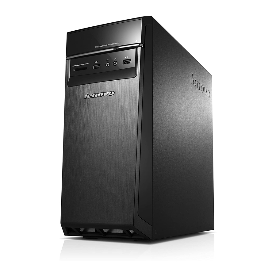
Page 7: Front View Of The Chassis
Front view of the chassis Attention: Be careful not to block any air vents on the computer. Blocked air vents can cause overheating. Hard disk drive indicator Power button Optical Drive (selected models only) Optical drive eject button Memory card reader (selected models only) USB 2.0 connectors (2) Headphone connector Microphone connector... -
Page 8: Rear View Of The Chassis
Rear view of the chassis (If the rear view configuration shown in this chapter is different from the rear of your computer, please refer to the rear of your computer.) H50-00 USB 3.0 connector On-board VGA connector USB 2.0 connectors (2) Ethernet connector Audio connectors Power connector... - Page 9 H50-05 On-board VGA connector HDMI connector (selected models only) USB 2.0 connectors (2) Ethernet connector USB 3.0 connectors (2) Audio connectors WiFi antenna (selected models only) Power connector Cable clip Expansion card slots (some models are equipped with graphics card, USB 3.0 or TV tuner card) User Guide...
- Page 10 H50-50 Power connector Voltage selection switch (selected models only) HDMI connector (selected models only) On-board VGA connector USB 3.0 connectors (2) USB 2.0 connectors (2) Ethernet connector Audio connectors WiFi antenna (selected models only) Expansion card slots (some models are equipped with graphics card, USB 3.0 or TV tuner card) User Guide...
- Page 11 H50-55 Power connector Voltage selection switch (selected models only) HDMI connector (selected models only) On-board VGA connector USB 3.0 connectors (2) USB 2.0 connectors (2) Ethernet connector Audio connectors WiFi antenna (selected models only) Expansion card slots (some models are equipped with graphics card, USB 3.0 or TV tuner card) Note: If your model has two VGA monitor connectors, be sure to use the connector on the graphics adapter.
-
Page 12: Basic Connector Instructions
Basic connector instructions Note: Your computer may not have all of the connectors described in this section. Connector Description Microphone Use this connector to attach a microphone to your computer when you want to record sound or if you use speech-recognition software. -
Page 13: Connecting Your Computer
Note: If your computer is equipped with a wireless keyboard or mouse, follow the installation instructions for those devices. Connecting your computer Use the following information when connecting your computer. • Look for the small connector icons on the back of your computer. Match the connectors to the icons. • If your computer cables and connector panel have color-coded connectors, match the color of the cable end with the color of the connector. Note: Your computer may not have all of the connectors described in this section. -
Page 14: 5.1 Audio Configuration Instructions
5.1 Audio configuration instructions This model of computer supports the transformation of stereo sound into 5.1 surround sound. Use the following guides when connecting to the 5.1 surround audio device: Blue line-in connector Surround Green line-out connector Front channel Pink Mic-in connector Center-LFE The configurations are as followings: 1. -
Page 15: Connecting The Power Cord
Connecting the power cord Connect the power cord to an electrical outlet. We recommend using a grounded connection or a surge protector. Some models are equipped with Power Adapter. User Guide... -
Page 16: Display Connecting Instructions When Playing Blu-Ray Discs
Display connecting instructions when playing Blu-ray Discs Note: Only some models are equipped with Blu-ray optical drive. Check the connectors available on your computer and display and select an appropriate cable according to the table below. Other types of cables do not meet the requirements of the Blu-ray standard. -
Page 17: Wireless Network Connection
Wired keyboard (selected models only) LVT —— After entering Windows, press this key to launch the LVT (Lenovo Vantage Technology) program, Lenovo’s pre-loaded Home PC software. In addition to its own functions, the LVT program will allow you to start other Windows compatible software specially configured to run on this model of computer. -
Page 18: Using Windows 8.1
Using Windows 8.1 This chapter contains the following topics: Switching between the main Windows 8.1 interfaces The Charms Bar Shutting down the computer Switching between apps Closing an app Opening other system programs Windows Help and Support Attention: The Windows 8.1 operating system is provided by Microsoft Corporation. -
Page 19: Switching Between The Main Windows 8.1 Interfaces
Switching between the main Windows 8.1 interfaces Windows 8.1 comes with two main user interfaces: the Start Screen and the Windows desktop. To switch from the Start Screen to the Windows desktop, do one of the following: • Select the Windows desktop tile on the Start Screen. • Press the Windows key + D. -
Page 20: Switching Between Apps
Switching between apps Sometimes you want to get back to an app you were just using, or quickly switch through your recent apps. To switch between apps: Move the cursor to the top left corner, then click to bring in the next app. (If your computer is equipped with touch screen, swipe in from the left edge of the screen to bring in the next app.) Closing an app... - Page 21 User Guide...
-
Page 22: Using The Rescue System
Using the Rescue System This chapter contains the following topics: OneKey Recovery Driver and Application Installation Attention: Using OneKey Recovery will result in loss of data. • You can restore the C: drive of the computer to factory default settings or to the last system backup status using OneKey Recovery. -
Page 23: Onekey Recovery
Note: The recovery files and relevant data used by the rescue system are saved in the service partition. If the service partition is deleted or damaged by someone other than authorized Lenovo service personnel, Lenovo will not be liable for any losses arising therefrom in any way. -
Page 24: Driver And Application Installation
Driver and Application Installation The Driver and Application Installation function in the rescue system provides a way for the user to conveniently reinstall all of the Lenovo applications and drivers that were shipped with your Lenovo hardware. Method 1: Automatic Installation Repeatedly press and release the F2 key once turning on the computer until the Lenovo Rescue System opens, then select Driver and Application Installation. - Page 25 User Guide...
-
Page 26: Using The Software
Using the Software This chapter contains the following topic: Software instructions Note: The interface and functionality of these features will depend on which software was shipped with the computer model you purchased. User Guide... -
Page 27: Lenovo Support
Lenovo Support The Lenovo Support program enables you to register your computer with Lenovo, download and view user manuals for your computer, get the warranty information of your computer, and explore help and support information. To open this program, do the following: Click the Lenovo Support icon from the Start Screen or Search Screen. -
Page 28: Troubleshooting And Confirming Setup
Troubleshooting and Confirming Setup This chapter contains the following topic: Troubleshooting and Problem Resolution User Guide... -
Page 29: Solving Problems
Solving Problems Follow these tips when troubleshooting your computer: • If you added or removed a part before the problem started, review the installation procedures to ensure that the part is correctly installed. • If a peripheral device does not work, ensure that the device is properly connected. • If an error message appears on the screen, write down the exact message. This message may help support personnel diagnose and fix the problem(s). • If an error message occurs in a program, see the Help document of this program. Troubleshooting Display Problems Problem: Blank screen or no image is displayed on the monitor. -
Page 30: Troubleshooting Audio Problems
2. Move any interfering devices away from the computer. 3. If the problem persists, contact Lenovo Service. Troubleshooting Audio Problems Problem: No sound from the integrated speakers. Troubleshooting and problem resolution: • Adjust the Windows volume control — select the speaker icon from the... -
Page 31: Troubleshooting Software Problems
1. Check to determine if there is an optical drive icon in the resource manager of the operating system. If not, restart your computer. If there is still no icon, contact Lenovo Service. Otherwise, continue with the next step of this procedure. -
Page 32: Special Considerations For Troubleshooting Windows
2. Confirm that the CD/DVD has been properly placed in the drive. If not, reload the CD or DVD. Otherwise, continue with the next step of this procedure. 3. Check the specifications that came with your computer to confirm that this optical drive is capable of reading this type of CD or DVD. -
Page 33: Windows Help And Support
Windows Help and Support If you have a problem with the operating system, see the Windows Help and Support file. To open the Windows Help and Support file, do one of the following: • Select the Settings charm, then select Help. • Press Windows key + F1. -
Page 34: Performing Daily Maintenance Tasks
Performing Daily Maintenance Tasks Cleaning the computer components Because many of the computer components consist of sophisticated integrated circuit boards, it is very important to periodically clean the computer to prevent dust buildup. The cleaning supplies you need to clean the components include: a vacuum cleaner, a soft cotton cloth, pure water (preferably purified or distilled water) and cotton swabs. - Page 35 User Guide...
-
Page 36: Hardware Replacement Guide
Hardware Replacement Guide This chapter contains the following topics: Locating components Identifying parts on the system board Removing the computer cover Removing and replacing the front bezel Replacing a memory module Replacing the hard disk drive ... - Page 37 Safety and Warranty Guide that was included with your computer. If you no longer have this copy of the Safety and Warranty Guide, you can obtain one online from the Support Web site at http://support.lenovo.com. User Guide...
-
Page 38: Additional Information Resources
You can find the following information: • CRU removal and installation information • Publications • Troubleshooting information • Parts information • Links to other useful sources of information To access this information, go to http://support.lenovo.com. Tools required To disassemble the computer, you need the following tools: • Wrist grounding strap and conductive mat for preventing electrostatic discharge • Flat screwdriver • Phillips screwdriver • Hex screwdriver... - Page 39 Handling static-sensitive devices Static electricity is harmless to you, but it can seriously damage computer components. When you are replacing a part, do not open the antistatic package containing the new part until the defective part has been removed from the computer and you are ready to install the new part.
-
Page 40: Locations
Locations This section provides illustrations to help locate the various connectors, controls and components of the computer. To remove the computer cover, refer to “Removing the computer cover”. Locating components The following illustration will help you to locate the various components in your computer. -
Page 41: Identifying Parts On The System Board
It provides basic computer functions and supports a variety of devices that are factory-installed or that you can install later. The following illustrations show the locations of parts on the system board. Lenovo H50-00 System fan header Microprocessor and heat sink... - Page 42 LPC debug header Front panel connector Power fan header Front USB connectors (2) Mini PCI-E slot Front audio connector Lenovo H50-05 Microprocessor and heat sink Microprocessor fan header Memory slots (2) Hard disk drive power connector Clear CMOS jumper Front panel connector...
- Page 43 PCI express X 1 adapter slot PCI express X 16 adapter slot Lenovo H50-50 12V power connector Microprocessor and heat sink Microprocessor fan header Memory slots (2) Thermal sensor header Hard disk drive power connector Power connector Power fan header...
- Page 44 PCI express X 16 adapter slot System fan header Battery Lenovo H50-55 12V power connector Battery System fan header Microprocessor and heatsink Microprocessor fan header Memory slots (2) Thermal sensor header Hard disk drive fan header Hard disk drive power connector...
-
Page 45: Replacing Hardware
PCI express X 16 adapter slot Front audio connector Replacing hardware Note: Use only parts provided by Lenovo. Removing the computer cover Attention: Turn off the computer and wait three to five minutes to let it cool down before removing the cover. - Page 46 5. Slide the computer cover to the rear of the chassis to remove it. Note: For this procedure, it helps to lay the computer on its side. User Guide...
-
Page 47: Removing And Replacing The Front Bezel
Removing and replacing the front bezel To remove and replace the front bezel: 1. Remove the computer cover. Refer to “Removing the computer cover”. Note: For this procedure, it helps to lay the computer on its side. 2. Remove the front bezel by releasing the three plastic tabs inside the chassis and pushing the bezel outward as shown. -
Page 48: Replacing A Memory Module
1. Remove the computer cover. Refer to “Removing the computer cover”. 2. Locate the memory module connectors. Refer to “Locating components”. For Lenovo H50-00 refer to the below instructions: 3. Remove the memory module being replaced by opening the retaining clips as shown. - Page 49 For Lenovo H50-05, H50-50 and H50-55 refer to the below instructions: 3. Remove the memory module being replaced by opening the retaining clips as shown. 4. Position the new memory module over the memory connector. Make sure the notch on the memory module is correctly aligned with the connector on the system board.
-
Page 50: Replacing The Hard Disk Drive
Replacing the hard disk drive To replace the hard disk drive: 1. Remove the computer cover. Refer to “Removing the computer cover”. Note: For this procedure, it helps to lay the computer on its side. 2. Disconnect the data and power cables from the hard disk drive. 3. -
Page 51: Replacing An Optical Drive
Replacing an optical drive To replace an optical drive 1. Remove the computer cover. Refer to “Removing the computer cover”. 2. Remove the front bezel. Refer to “Removing and replacing the front bezel”. 3. Disconnect the data and power cables from the rear of the optical drive. 4. -
Page 52: Replacing The Card Reader Module
Replacing the card reader module To replace the card reader module 1. Remove the computer cover. Refer to “Removing the computer cover”. 2. Remove the front bezel. Refer to “Removing and replacing the front bezel”. 3. Disconnect the card reader data cable from the connector on the motherboard. 4. -
Page 53: Replacing A Pci Express Adapter
Replacing a PCI express adapter To replace an adapter: 1. Remove the computer cover. Refer to “Removing the computer cover”. 2. Remove the screw that secures the latch to the chassis, open the adapter latch and remove the adapter by pulling it straight out of the adapter connector. - Page 54 3. Install the new adapter into the same adapter connector. 4. Ensure the adapter is fully seated into the adapter connector. 5. Screw the latch into the chassis. 6. Refer to “Completing the installation”. User Guide...
-
Page 55: Replacing The Keyboard And Mouse
Replacing the keyboard and mouse To replace the keyboard: 1. Remove any media (disks, CDs, or memory cards) from the drives, shut down the operating system, and turn off the computer and all attached devices. 2. Unplug all power cords from electrical outlets. 3. -
Page 56: Completing The Installation
Completing the installation After replacing a part or parts, you must close the computer cover and reconnect all the cables, including telephone lines and power cords. Some parts will require confirming updated information in the Setup Utility program. Refer to “Starting the Setup Utility”... - Page 57 “Locating connectors on the front of the computer” and “Locating connectors on the rear of the computer”. Note: In most areas of the world, Lenovo requires the return of the defective CRU. Information about this will come with the CRU or will come a few days after the CRU arrives.
-
Page 58: Appendix
Thank you for using Lenovo products. Carefully read all documents shipped with your computer before you install and use the product for the first time. Lenovo is not responsible for any loss except when caused by installation and operations performed by Lenovo professional service personnel. -
Page 59: Trademarks
Trademarks Lenovo and the Lenovo logo are trademarks of Lenovo in the United States, other countries, or both. Microsoft, Windows, and Windows Vista are trademarks of the Microsoft group of companies. Intel Inside is a trademark of Intel Corporation in the U.S. and/or other countries. -
Page 60: Enabling Erp Compliance Mode
For more information about ENERGY STAR, go to: http://www.energystar.gov. Lenovo encourages you to make efficient use of energy an integral part of your day-to-day operations. To help in this endeavor, Lenovo has preset the following... -
Page 61: Electronic Emissions Notices
Additional information as required by EU Regulation 617/2013 implementing Directive 2009/125/EC with regard to ecodesign requirements for computers and computer servers can be found here: www.lenovo.com/ecodeclaration. Electronic emissions notices The following information refers to Lenovo machine type: • 90BF • 90BG • 90B6 • 90B7... -
Page 62: Mexico Regulatory Notice
Lenovo is not responsible for any radio or television interference caused by using other than recommended cables or connectors or by unauthorized changes or modifications to this equipment. Unauthorized changes or modifications could void the user’s authority to operate the equipment. - Page 63 User Guide...
Need help?
Do you have a question about the H50 Series and is the answer not in the manual?
Questions and answers