Advertisement
Quick Links
Advertisement

Related Manuals for AAton A-Minima


Summary of Contents for AAton A-Minima
- Page 1 u s e r ’ s g u i d e...
- Page 2 presentation...
- Page 3 - Built-in Intervalometer - Back light display - 200' quick change magazines, 'B' wound rolls in Aaton's ~flexi- ble~ daylight spools (standard metallic 200 spools and 400' reels, NO) "Temporary casting" is engraved on the initial cameras. This hous- ing will be exchanged when the Video Assist becomes available.
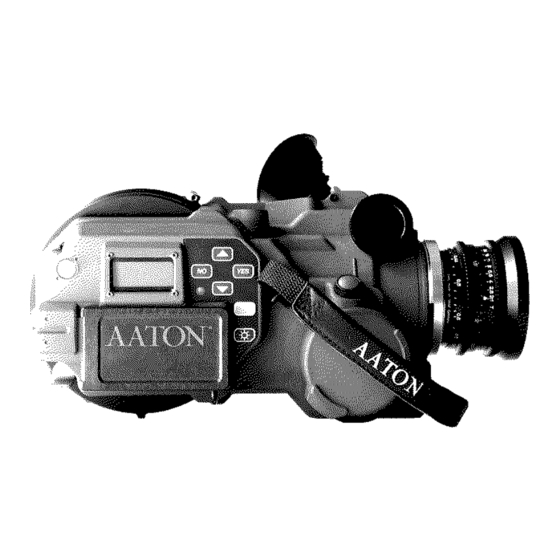
- Page 4 1 - Magazine release lever 1 - Viewing screen collimation port 9 - Shutter trigger 2 - Lightmeter dome 2 - gate rear pressure plate 10 - Magazine release lever 3 - Backlight LCD display 3 - Film pulldown claw 4 - Batteries compartment 4 - Take-up sprocket door 5 - LED camera and timecode status indicator...
- Page 5 1 - Diopter locking knob 1 - Camera rubber eyecup 2 - PL lens port locking ring 2 - magazine feed side 3 - A-minima fixed viewing screen 3 - magazine take-up side 4 - camera 172.8°mirror/shutter 4- Lightmeter dome...
- Page 6 1 - Diopter locking knob 1 - 3/8-16 mounting hole 2 - Magazine latch 2 - Lemo 6 Aaton power base connection 3 - 3/8-16 insert 3 - power base locating hole 4 - camera run switch 4 - Magazine hinge...
-
Page 7: Control Panel
control panel... - Page 8 Chapter 2 - The A-Minima Control Panel A-Minima control panel The A-Minima control panel consist of an illuminated LCD display, six buttons to access and adjust all operator functions, and a camera status LED. Each buttons can have a different function, depending on the mode you are in.
- Page 9 200 ft From the Aaton Power Base : Simply use the Aaton wooden handgrip and connect it to the Lemo2 connector located between the two front rod inserts of the power - If the Aatoncode has been initialized in the camera, either from the base.
- Page 10 UP or DOWN key to go through the speed selection, press YES to validate your choice. To modify a specific speed, added to the preset speed list: A-minima allows you to modify or delete this speed. If you want to 24.000 speed= preset modify it, access the speed menu, then choose "MODIFY"...
- Page 11 Chapter 2 - The A-Minima Control Panel Chapter 2 - The A-Minima Control Panel To delete a specific speed added to the preset list ASA setting If you want to deleted it from your preset list, choose DELETE, then press YES. The camera will default to 1.000 fps.
- Page 12 DOWN key then press YES. First select the year with the exposed onto the film by means of seven micro diodes located into UP or DOWN key, press YES to validate, A-minima will take you the gate of the camera, near the camera pulldown claw. These to each timecode field.
- Page 13 If the GMT or audio device is not powered, or if the cable is faulty the camera will display NO ANSWER. A-minima can be used to monitor timecode after it has been initial- • Using the OriginCplus : (please refer to the OC+ manual in order to program it)Make sure ized in another device.
- Page 14 In 16mm, a full 200 feet roll contains 8000 frames. When viewed at In the intervalometer mode, the A-Minima operates at a constant 24 frames per second, a roll last approx 5 minutes and 30 seconds. rate of 2 frames per second. The shutter opening being a fixed 172,8...
- Page 15 Chapter 2 - The A-Minima Control Panel Display light shutter : Go to the A-MINIMA OPTIONS menu, then press YES to enter. In order to save battery power, the A-minima display backlight can COUNTER flashes, press the DOWN key to select SHUTTER, be turned off.
- Page 16 LED flashes and a "NO EXT SYNC" message is displayed. Please contact your Aaton representative or rental house for further information concerning cables wiring. Camera master: to control another A-Minima speed and shutter.
- Page 17 magazine...
- Page 18 The magazine coaxial design utilizes two identical spools, one on each side. The A-minima spools are "daylight friendly". If you load and down- load your magazine in daylight, you will exposed approximately 5 ft of film during loading and 2 ft of film when taking the magazine off the camera body.
-
Page 19: Loading The Magazine
Chapter 3 - Loading the A-Minima When engaging the mag onto the camera, the magazine shutter opens, allowing the two flexible spools to come in contact and be driven by the camera take-up and feed sprockets. In this position, both spools are spread apart to ensure a clean and silent passage for the film. - Page 20 Chapter 3 - Loading the A-Minima Installing the loaded magazine and threading the A-minima. Before installing the magazine, adjust the loop length by pulling it to the beginning of the magazine hinge. Also, on the camera body, open the feed and take-up sprocket door by simply pushing them away from the sprockets (fig 1).
- Page 21 Chapter 3 - Loading the A-Minima Pull the magazine locking lever to release the magazine, close the camera door and re-engage firmly the magazine into position. Press on the upper arrow to re-engage the claw and set your camera shutter in the reflex viewing position.
- Page 22 connectors...
- Page 23 Chapter 4 - Connectors Connectors The A-minima uses three connectors for power and accessory input Following is a detailed list, location and main function of each. The Lemo 6 connector located at the rear of the camera is the main accessory connection of the A-minima.
- Page 24 accessories...
- Page 25 Chapter 5 - Accessories A-Minima Power Base When used in conjunction with the A-minima camera body, the Aaton small power base extends the camera functions.without com- promising its size, weight. and ease of use. The power base is multi functional: as a tripod intermediary plate, it accepts a standard 15mm or 19mm sliding bridgeplate for building the camera system for studio work.
- Page 26 Chapter 5 - Accessories Use the 3/8" screw to attach the Aaton power base to the bottom of the camera body. A 5mm locating pin insures the correct lateral positioning of the camera. - The XLR4 connector located on the operator side is the main 12 volts power input.
- Page 27 Aaton power base installed on the A-minima body, not from the internal disposable batteries. The A-minima video assist has two separate video outputs. One is a standard BNC connector, the other one is a small Fisher4 connector used for a small mini LCD monitor.
- Page 28 Chapter 5 - Accessories Through the hole located on the upper left corner of the camera lens port, carefully loosen the tightening screw used to later hold the video lens onto the camera internal tubular holder. Do not unscrew it completely as it could fall into the camera hous- ing.
- Page 29 Be careful not to pull on the BNC cable as you could damage the video electrical connections. Power the A-minima and turn on the video assist. You should see a picture of the viewing screen on the monitor. Open the video lens iris by moving its lever towards the rear of the A- Minima.
Need help?
Do you have a question about the A-Minima and is the answer not in the manual?
Questions and answers