Table of Contents
Advertisement
Quick Links
CALIFORNIA PUBLIC UTILITIES
COMMISSION
Advice Letter Filing Summary Sheet
:
AT&T
Company Name
:
525 Market Street, #1944
Address
San Francisco, CA 94105
City, State, ZIP:
Filing #:
37837
Name:
Mary Liz DeJong
Tariff Schedules:
For Contract Keyword, Type: Government
Subject of filing:
(Service(s) included)
Authorization for filing:
(Resolution #, Decision #, etc.)
Affected services:
(Other services affected, pending or replacement AL filings)
Rate Element(s) affected and % change:
(Non-recurring and / or recurring)
Customer Notice Required (if so, please attach)
Notes/Comments:
(Other information & reference to advice letter, etc.)
File Protest and/or Correspondence to:
Director, Communications Division
505 Van Ness Ave., San Francisco, CA 94102
and if you have email capability, ALSO email to:
TD_PAL@cpuc.ca.gov
Protest also must be served on utility:
(see utility advice letter for more information)
Resolution Required
Executive Action Resolution Req'd.
TD Suspension on: ___ / ____ / ____
Comm. Suspension on: ___ / ___ / ___
Resolution No.: T - ____________
Rev. 09/24/07
(PAL)
California
Requested
Effective Date
Email Address:
regtss@att.com
regtss@att.com
(Name, email address & Phone and FAX numbers are Required for "Filer")
N/A
Other
Backup Power – Customer Education
D.10-01-026
(Date Filed / Received Stamp by CPUC Industry Division)
Date AL served on parties: July 20, 2010
July 20, 2010
:
Keyword:
Date Executed
GRC-LEC = Cost of Service LEC Carrier
URF-Carrier = Uniform Regulatory Framework Carrier
(see D.06-08-030/D.07-09-019)
OTHER = Wireless (CMRS) Carrier
(FOR CPUC USE ONLY)
Supv. / Analyst ________________ / ________________
Due Date to Supv.: _______________________________
Analyst Completion Date: _________________________
Supervisor Approval Date: ________________________
AL / Tariff Effective Date: _________________________
Notes: ___________________________________________
CPUC Utility Number U -
GRC-LEC
Commission Resolution Requested
Carrier of Last Resort (See D.96-10-066)
AL Tier I
Phone No.:
(415) 778-1299
(415) 778-1299
Compliance
Contract
Total Rev ($)
1001-C
URF-Carrier
Other
II
III
Fax No.:
(415) 543-3766
No. Tariff
Sheets: 0
Advertisement
Chapters
Table of Contents

Subscribe to Our Youtube Channel
Related Manuals for AT&T DC UPS

Summary of Contents for AT&T DC UPS
- Page 1 (Date Filed / Received Stamp by CPUC Industry Division) CALIFORNIA PUBLIC UTILITIES COMMISSION Advice Letter Filing Summary Sheet Date AL served on parties: July 20, 2010 (PAL) AT&T 1001-C Company Name California CPUC Utility Number U - 525 Market Street, #1944 Address GRC-LEC URF-Carrier...
- Page 2 AT&T California regtss@att.com 525 Market Street Room 1944 San Francisco, CA 94105-2727 www.att.com July 20, 2010 U 1001 C Advice Letter No. 37837 Public Utilities Commission of the State of California This advice letter is filed in compliance with Ordering Paragraph 2 of Decision (D.)10-01-026, which requires facilities-based providers of telephony services who provide service to residential customers using coaxial cable, fiber-optic cable or other technologies that require backup power on the customer’s premises to file an information-only compliance advice letter detailing their customer education programs that comply...
- Page 3 AT&T California Advice Letter Service List Via U.S. Mail Shascom 9-1-1 Shascom 9-1-1 Tyco Electronics Power Systems Integra Telecom Holdings, Inc. Joy Willis Kathy Galey Natasha Hood Sheila Harris Operations Manager Systems Administrator 2043 Loggia Manager, Government Affairs 3101 South Street 3101 South Street Newport Beach, CA 92660-9039 1201 NE Lloyd Blvd., Ste.
- Page 4 AT&T California Advice Letter Service List Page 2 Via e-mail robertg@greenlining.org bfs@cpuc.ca.gov jweiss@scottsvalley.org crs@cpuc.ca.gov jwilson@scottsvalley.org cg2@cpuc.ca.gov rdelsman@nextgnetworks.net jpo@cpuc.ca.gov ysmythe@caltel.com bor@cpuc.ca.gov richard.goldberg@dgs.ca.gov mg1@cpuc.ca.gov g.gierczak@surewest.com psp@cpuc.ca.gov renato.peruzzi@dts.ca.gov prw@cpuc.ca.gov daphne.rhoe@dgs.ca.gov raw@cpuc.ca.gov larry.rowe@dgs.ca.gov snr@cpuc.ca.gov mike@edelsteingilbert.com rsm@cpuc.ca.gov jlites@schottlites.com sim@cpuc.ca.gov mrubalcava@schottlites.com tch@cpuc.ca.gov Susan.Lipper@T-Mobile.com vfb@cpuc.ca.gov steve@shascom911.com edward.randolph@asm.ca.gov ayo@cpuc.ca.gov pcl@cpuc.ca.gov...
- Page 5 MATERIALS PROVIDED TO NEW CUSTOMER BY TIME OF INSTALLATION Important Customer Information Regarding your AT&T Voice and Internet Service Traditional Telephone Service over Fiber to the Premises AT&T DC UPS Operation Manual CyberPower PSU U-verse Voice Back-up Power for RG & ONT...
- Page 6 ATTACHMENT A Important Customer Information Regarding your AT&T Voice and Internet Service Please retain for your records Required Optical Network Terminal Battery Backup Power Your AT&T voice and Internet services require electrical power from your home to operate. Electricity from your home powers the Optical Network Terminal (ONT), an equipment box where AT&T’s fiber network terminates and inside wiring for your home originates.
- Page 7 ATTACHMENT A The alarm can be silenced for 24 hours by pushing the blue button on the front of the power supply. The Missing Battery status light will be green if no battery is connected to the power supply. For more information see the owner’s manual: att.com/batterybackup. CyberPower PSU: There are status lights on the front right of the CyberPower PSU.
- Page 8 ATTACHMENT A AT&T DC UPS Operation Manual (Leave with Customer) DC UPS Operation Manual, Rev 1.0 Page: 1 of 8 ATTACHMENT A - Page 3 of 33...
-
Page 9: Table Of Contents
USTOMER ATTERY EPLACEMENT TABLE OF FIGURES Figure 1: DC UPS Power Supply and ONT System Configuration ........................3 Figure 2: Warning Label .......................................5 Figure 3: DC UPS Front Panel LEDs and Control ..............................6 Figure 4: DC UPS Front Panel LEDs ...................................7 Figure 5: Battery Replacement ...................................8... -
Page 10: Product Introduction
POTS and Ethernet services in the ONT. Alarm outputs are available on the DC UPS to monitor the status of the backup battery (On/Low/Faulty/Missing). The DC UPS indicates its status to the resident with LEDs and audible alarms and to the outdoor ONT by a signal return connection. -
Page 11: Important Safety Notes
Check that the power cord(s), plug(s), and outlets are in good condition. No user serviceable components other then the battery are present in the DC UPS. Battery Warnings Battery Warranty is top-charge date plus thirty-six months. Replacement battery should be PX12072F2-HG. -
Page 12: Safety Warning Label
Voice, 911 Dialing, and Battery Charging” attached to the cord. DO NOT UNPLUG! – Power Supply for Voice, 911 Dialing, and Battery Charging. Figure 2: Warning Label DC UPS Operation Manual, Rev 1.0 Page: 5 of 8 ATTACHMENT A - Page 7 of 33... -
Page 13: Control
Figure 3: DC UPS Front Panel LEDs and Control One user control is present in the form of one blue button on the front cover of the DC UPS. This alarm-silence button will quiet the audible alarm for 24 hours. After 24 hours the alarm will reactivate if the fault condition has not been corrected. -
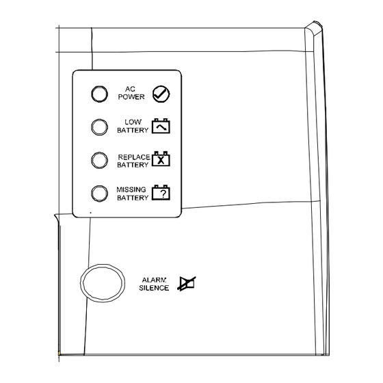
Page 14: Operational Leds
ATTACHMENT A Operational LEDs Figure 4: DC UPS Front Panel LEDs Four status LEDs are displayed on the front panel of the DC UPS. The operation of the DC UPS can be assessed using these LEDs. Table 2: LED Indicators... -
Page 15: Maintenance
Battery replacement is detailed on a label located inside the front cover of the DC UPS. Remove the Battery: 1. Open the front cover of the DC UPS by depressing the tab located at bottom of unit. 2. Detach the Velcro and pull out the old battery. - Page 16 ATTACHMENT A CyberPower ATT36A12V3S (Leave Behind Manual) CyberPower ATT3612V3S (Leave Behind Manual) Page: 1 of 11 ATTACHMENT A - Page 11 of 33...
-
Page 17: Table Of Contents
ATTACHMENT A TABLE OF CONTENTS PRODUCT INTRODUCTION .........................3 ........................3 ENERAL ESCRIPTION ..........................3 OMPONENTS IMPORTANT SAFETY NOTES......................4 ........................4 LECTRICAL ARNINGS ........................4 ATTERY ARNINGS ......................5 AFETY ARNING ABEL POWER SUPPLY OVERVIEW ......................6 ............................6 VERVIEW OPERATION ............................7 ............................7 TART ...........................7 ONTROLS ........................7 PERATIONAL ....................8 UXILLARY OWER... -
Page 18: Product Introduction
ATTACHMENT A PRODUCT INTRODUCTION General Description The ONT-BBPSU (Optical Network Terminal Uninterruptable Battery Backup Power Supply Unit) is designed to be mounted inside a customer premises and provides power to the ONT. The Optical Network Terminal (ONT) is an equipment box typically installed on the outside of your home, where the fiber network terminates and the inside wiring for your home originates. -
Page 19: Important Safety Notes
ATTACHMENT A IMPORTANT SAFETY NOTES ONLY qualified installation and repair personnel should service this power supply. SAVE THESE INSTRUCTIONS - This manual contains important instructions for the ATT3612V3S units that should be followed during installation and maintenance. Verify the supplied AC line voltage prior to installation using an AC voltage meter. ... -
Page 20: Safety Warning Label
ATTACHMENT A Wear protective clothing and eye protection whenever installing, maintaining, servicing, or replacing batteries. If any battery emission contacts the skin, immediately and thoroughly wash with water. Follow approved chemical exposure procedures. Neutralize any spilled battery emission with the special solution contained in an approved spill kit or with a solution of one pound Bicarbonate of soda to one gallon of water. -
Page 21: Power Supply Overview
ATTACHMENT A POWER SUPPLY OVERVIEW Overview Figure 3: Unit Overview (Front) 1. Control Buttons (Alarm Silence) 2. LED Indicators (System Status/Battery Power/Replace Battery/Auxiliary Power Source) 3. Battery Input Power Connector 4. 7 Pin Connector 5. AC Power Cord Inlet 6. Strain Relief and Cable Tie for DC Power Cable 7. -
Page 22: Operation
ATTACHMENT A OPERATION Start-Up Make sure that the battery connector is plugged in, the battery is locked into place, and the battery door is closed. Plug the ATT3612V3S power supply into AC power. The LED of system status showing green indicates normal mode of operation. The unit is now ready to be placed into service. -
Page 23: Auxillary Power Connection
ATTACHMENT A Auxillary Power Connection Figure 5: Auxiliary Power Connection Connection point for customer-supplied DC input voltage shall be 12Vdc. After depleting the on- board battery capacity, the ATT3612V3S will utilize power from a valid and present external source. The auxiliary power source supplies power to the load (ONT) in the event of AC input voltage failure and a depleted battery. -
Page 24: Maintenance
ATTACHMENT A MAINTENANCE Maintenance Mode Maintenance mode determines remaining useful battery life. If the remaining battery life is determined to be below an acceptable level and unable to support proper operation, the Replace Battery LED will be illuminated. - The ATT3612V3S enters the maintenance mode approximately once every 45 days. - In the event that ATT3612V3S is in the maintenance mode and an AC failure occurs, maintenance mode will cease and the ATT3612V3S will supply the power to the load. - Page 25 ATTACHMENT A ← Step 3: a. Remove the harness from the old battery and place on the new battery with the red and black Faston terminals, observing correct polarity, Figure 8 then reconnect the two-position locking connector. b. Slide the battery back into the compartment and make sure it latches.
-
Page 26: Specifications
ATTACHMENT A SPECIFICATIONS Table 4: Specifications CyberPower ATT3612V3S (Leave Behind Manual) Page: 11 of 11 ATTACHMENT A - Page 21 of 33... - Page 27 ATTACHMENT A U-verse Voice Back-up Power for RG & ONT Historically, telephone service has been powered by electrical power within the telephone network. Your AT&T U-verse Voice service, including 911 dialing, requires electrical power and will not function during a power outage without battery backup power at your premises;...
- Page 28 ATTACHMENT A The OPTICAL NETWORK TERMINAL (ONT) is a box typically located on the side of your house or in your garage, where AT&T’s fiber network terminates. Please refer to the pictures below to determine whether you have an ONT. The ONT also requires electrical power from your home to operate, which you are responsible for providing.
- Page 29 ATTACHMENT A Residential Gateway (RG) and Battery Backup Unit (BBU) Backup Battery for RG: AT&T provides an initial RG battery backup unit, with an initial backup battery, for purchasers of AT&T U-verse Voice service. When equipped with a new, fully charged backup battery, it will provide approximately four hours of battery backup power.
- Page 30 ATTACHMENT A the audible alarm will sound every two seconds when the battery needs replacing. This alarm warns that the battery has reached the end of its useful life and the user must replace the battery as soon as possible to ensure proper operation of the RG battery backup How do I replace the RG battery: Remove the battery door on the rear of the device.
- Page 31 ATTACHMENT A which can be placed within 100 feet of the ONT and is installed inside your home or garage. AT&T supplies an initial backup battery in the PSU for the first resident of the premises where AT&T services are installed. All subsequent backup batteries are the responsibility of the customer at the premises.
- Page 32 ATTACHMENT A at 1.800.472.2879 or www.gsbattery.com. Be sure to have the battery model number warranty date available which is located on the label on the side of the battery available, which is PX12072- HG. The battery number is also located on the label on the side of the battery.
- Page 33 ATTACHMENT A PSU’s. To determine the model number, loosen the screws in the battery compartment located at the bottom left of the PSU, lift the PSU up, and look at the model number on the back of the unit. How to determine when to replace your ONT battery: Delta One Piece PSU: There are status lights on the front right of the Delta One Piece PSU.
- Page 34 ATTACHMENT A To determine if the battery is missing, open the door and look for a battery. APC PowerShield PSU Model # CP27U13: There are status lights on the front right of the APC PSU. Refer to the Battery Status light. It will be red if the battery needs to be replaced or if it is missing.
- Page 35 ATTACHMENT A U-verse Voice Back-up Power for iNID Historically, telephone service has been powered by electrical power within the telephone network. Your AT&T U-verse Voice service, including 911 dialing, requires electrical power and will not function during a power outage without battery backup power at your premises;...
- Page 36 ATTACHMENT A structure – garage, closet or basement (iPSU). The iPSU includes a backup battery and usually will be located near where power comes into your home. The iPSU must be located within 100 feet of where AT&T’s network terminates. If the iPSU is located in an area that you do not use regularly, you should check the status of the iPSU periodically to ensure that you receive any visual or audible warnings regarding the condition of the iPSU...
- Page 37 ATTACHMENT A Voice service, you will not have an initial backup battery from AT&T, therefore, you should check the iNID Power Supply for the presence and status of a backup battery and place/replace if necessary). For battery replacement and recycling information and to purchase replacement batteries, please call EnerSys at 1-866-327-5755 or visit the website www.fibersafebattery.com.
- Page 38 ATTACHMENT A How do I replace the iPSU battery? Use a Phillips screwdriver to unfasten two screws (one on each side) securing the power supply battery cover. Press down on the tension springs and pull to disconnect the battery cable connector from the battery cable.
- Page 39 ATTACHMENT B ATTACHMENT B - ANNUAL NOTICE TRADITIONAL TELEPHONE SERVICE OVER FIBER TO THE PREMISES Bill page message: BATTERY BACKUP INFO Your telephone service requires electrical power from your home to operate. If a power outage occurs, you will not be able to make or receive calls, including 911 calls, unless you have battery backup power. You are responsible for maintaining battery backup power.
- Page 40 ATTACHMENT B Important Battery Backup Information Regarding your AT&T Voice and Internet Service, including owner manuals. Please retain for your records. Required Optical Network Terminal Battery Backup Power Your AT&T voice and Internet services require electrical power from your home to operate. Electricity from your home powers the Optical Network Terminal (ONT), an equipment box where AT&T’s fiber network terminates and inside wiring for your home originates.
- Page 41 ATTACHMENT B How to tell when to replace your battery Delta One Piece PSU: There are status lights on the front right of the Delta One Piece PSU. Refer to the Replace Battery and Missing Battery status lights. The Replace Battery status light will be red if the battery needs to be replaced.
- Page 42 ATTACHMENT B Replacing the Battery Open the door, carefully pull the battery off the shelf and remove the black and red wires. Connect the black (-) and red (+) wires onto the new battery noting the proper battery polarity. Slide the new battery onto the shelf and secure.
- Page 43 ATTACHMENT B U-VERSE VOICE Post card message: We hope you are enjoying your AT&T U-verse service. We wanted to remind you that in the event of a power outage, you will need battery backup power for your AT&T U-verse Voice service, including 911, to function properly.
- Page 44 ATTACHMENT B Master Battery Page: URL att.com/newbattery U-verse Voice Back-up Power for RG, ONT & iNID Historically, telephone service has been powered by electrical power within the telephone network. Your AT&T U-verse Voice service, including 911 dialing, requires electrical power and will not function during a power outage without battery backup power at your premises;...
- Page 45 ATTACHMENT B Broadband Network: AT&T U-Verse Voice is provided to you over a broadband (Internet Protocol or "IP") network. If there is a broadband network outage, your AT&T U-verse Voice service will not function and you will not be able to make 911 calls with this service. AT&T recommends that you always have an alternative means of accessing 911 during a broadband outage, such as via a cellular phone.
- Page 46 ATTACHMENT B General battery information: General battery information General battery information: http://www.att.com/u- and Owners manual: http://www.att.com/u- verse/explore/battery-backup.jsp http://www.att.com/u- verse/explore/battery-backup.jsp Owners manual: verse/explore/terminal- Owners manual: www.belkin.com/gatewaybattery backup.jsp http://www.fibersafebattery.com ATTACHMENT B - Page 8 of 19...
- Page 47 ATTACHMENT B Battery Backup page (RG and iNID): URL http://www.att.com/u-verse/explore/battery-backup.jsp AT&T U-verse Battery Backup AT&T U-verse Voice, like other Voice over Internet Protocol ("Voice over IP" or "VoIP") services, requires electrical power at your home to operate. Depending on your service address, your AT&T U-verse Voice service will include either a Residential Gateway Battery Backup Unit ("BBU") or an iNID Power Supply Unit ("iPSU").
- Page 48 ATTACHMENT B Residential Gateway (RG) and Battery Backup Unit (BBU) Backup Battery for RG AT&T provides an initial RG battery backup unit, with an initial backup battery, for purchasers of AT&T U- verse Voice service. When equipped with a new, fully charged backup battery, it will provide approximately four hours of battery backup power.
- Page 49 ATTACHMENT B Local hardware stores Battery Plus Sears How to determine when to replace your RG battery The yellow LED on the front panel will flash and the audible alarm will sound every second which indicates a low battery. This alarm will continue until the unit performs a forced shutdown when the battery is depleted. The red LED on the front panel will flash and the audible alarm will sound every two seconds when the battery needs replacing.
- Page 50 ATTACHMENT B Please note that AT&T U-verse Voice will work only in your home. You will not be able to make any calls, including 911 calls, from any other location, even if you move the Residential Gateway (RG) or an external Telephone Adapter (TA) to the new location.
- Page 51 ATTACHMENT B Figure 1 Backup Battery for iNID Power Supply Unit (iPSU) AT&T provides an initial iNID Power Supply battery backup unit for the first purchaser of AT&T U-verse Voice service. All subsequent backup battery replacements are the responsibility of the customer at the premises. (If you are not the first purchaser of AT&T U-verse Voice service, you will not have an initial backup battery from AT&T, therefore, you should check the iNID Power Supply for the presence and status of a backup battery and place/replace if necessary).
- Page 52 ATTACHMENT B Consumer batteries are only available for purchase from EnerSys at 1-866-327-5755 or www.fibersafebattery.com. How to determine when to replace your iPSU battery When the battery needs to be replaced, a chirp sounds intermittently unless you press the button to silence it for 12 hours.
- Page 53 ATTACHMENT B Typical battery backup time for the BBU or iPSU is 4 hours with a new, fully charged battery, with one corded single-line touchtone phone connected to the AT&T U-verse Residential Gateway directly or through your in-home wiring, and with no other equipment and no service other than AT&T U-verse Voice service drawing power from the Battery Backup.
- Page 54 ATTACHMENT B Terminal Backup page (ONT): URL http://www.att.com/u-verse/explore/terminal-backup.jsp AT&T U-verse® Terminal Backup ONT Battery Backup If you have a Residential Gateway (RG) inside your premises, you may also have an Optical Network Terminal (ONT) which is a box typically located on the side of your house or in your garage, where AT&T's fiber network terminates.
- Page 55 ATTACHMENT B Delta One Piece PSU Delta Two Piece PSU CyberPower PSU APC PowerShield PSUs (Two models that look the same; model numbers CP24U12 & CP27U13) Backup Battery for ONT: You are responsible for monitoring the backup battery and will need to replace it when necessary.
- Page 56 ATTACHMENT B Sears Amazon (via Internet) Determine the Power Supply Unit (PSU) type On the front of Power Supply Unit (PSU) is a label that shows the Serial Number designated by S/N. If the S/N starts with DAE this is a Delta PSU. If the S/N starts with CYB this is a CyberPower PSU. Two models that look the same are the APC PowerShield PSUs.
- Page 57 ATTACHMENT B APC PowerShield PSU Model # CP24U12: There are status lights on the front right of the APC PSU. Refer to the Battery Status light. It will be red if the battery needs to be replaced or if it is missing. There is no audible alarm on this unit. To determine if the battery is missing, open the door and look for a battery.
Need help?
Do you have a question about the DC UPS and is the answer not in the manual?
Questions and answers