Table of Contents
Advertisement
Advertisement
Table of Contents

Related Manuals for Aeroneb Solo System

Summary of Contents for Aeroneb Solo System
- Page 1 Instruction Manual Symbols for Page 8 and 9 30(mins.) Rx Only...
- Page 3 Aeroneb Solo System ® Instruction Manual Part Number: AG-AS3050-EN Rev. J © 2011 Aerogen Ltd.
- Page 4 This page has been intentionally left blank...
-
Page 5: Table Of Contents
Installation for use with a mask........25 Installation for use with a mouthpiece......26 Adding medication Nebulization Functional test Cleaning of Pro-X Control Module Troubleshooting Order numbers Specifications Physical Environmental Performance Power Appendix 1 EMC tables Aeroneb Solo System Instruction Manual ®... - Page 6 Figure 2: Aeroneb Pro-X controls and indicators ® Figure 3: Connecting nebulizer unit to T-piece Figure 4: Connecting control module and nebulizer unit Figure 5: Connecting the Aeroneb Pro-X AC/DC adapter 15 ® Figure 6: Connecting tubing and syringe to the Aeroneb Solo for continuous nebulization ®...
-
Page 7: Introduction
Introduction The Aeroneb Solo System is an iteration of the Aeroneb ® ® Professional Nebulizer System. The indications for use of the Aeroneb Professional Nebulizer System are given ® below. The Aeroneb Solo System, which consists of the ® Aeroneb... -
Page 8: System Description
System description The Aeroneb Solo System (Figure 1) includes the following ® components: nebulizer unit (aerosol generator and plug), T-piece (adult)*, Aeroneb Pro-X control module, control cable, ® AC/DC adapter and mounting brackets. (Pedatric & neonate adapters and continuous nebulization tube set are sold separately). - Page 9 The T-piece securely connects the nebulizer unit into the breathing circuit. The T-piece connections are standard male and female 22mm conical ports and connect to standard patient breathing circuits. Aerogen recommends that the Aeroneb Solo ® nebulizer be used in conjunction with a relevant disposable T-piece supplied by Aerogen.
- Page 10 A universal mounting bracket clamps the control module to standard IV poles and medical rail systems. An equipment mount adapter mounts the control module on standard equipment mounts. Aeroneb Solo System Instruction Manual ®...
-
Page 11: Warnings
Warnings Read and study all instructions before using the Aeroneb Solo system. Only medical personnel should ® operate the device. Perform functional test prior to use to ensure correct operation (see page 30). This is a single patient use device not to be used on more than one patient to prevent cross infection. - Page 12 Do not use in the presence of a flammable anesthetic mixture combined with air or with oxygen or nitrous oxide. Do not use the Aeroneb Solo in conjunction with the administration of volatile anaesthetics as this may have an adverse effect on the Aeroneb Solo nebuliser or T-piece plastics.
-
Page 13: Electromagnetic Susceptibility
Follow local laws and recycling plans regarding disposal or recycling of components, batteries and packaging. The Aeroneb Solo nebulizer is designed for use in continuous ® mode only when used with the Aeroneb Pro –X controller. ® Do Not use the Aeroneb Pro Nebulizer in continuous mode. - Page 14 Aeroneb Solo nebulizer system. ® • Do not use the Aeroneb Solo adjacent to or stacked ® with other equipment. If adjacent or stacked use is necessary, the device should be observed to verify normal operation in this configuration.
-
Page 15: Symbols
Symbols The following symbols apply to Aeroneb Solo nebulizer and ® Aeroneb Pro-X controller. These symbols appear on the back ® of the control module and on the packaging: Table 1: Aeroneb Solo System Symbols ® Symbol Meaning Serial number, where YY is the year of... - Page 16 This device complies with the requirements of the Medical Devices Directive (93/42/EEC). Non-Sterile STERILE Consult Instructions for Use Use by (YYYY-MM) Manufacturer Batch Code Serial Number Catalogue Number Single Patient Use, Do not reuse Aeroneb Solo System Instruction Manual ®...
-
Page 17: Controls And Indicators
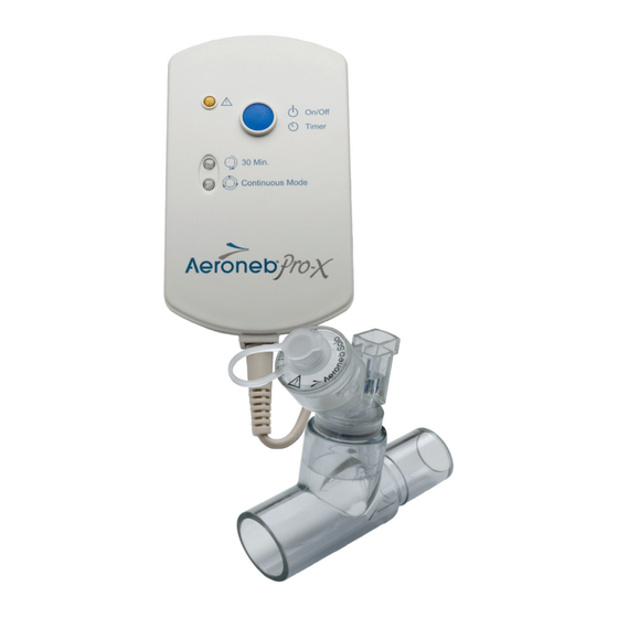
Cable Input International Controller On/Off Power Fault Indicator 30 Min. Timer Selection Indicator Battery Status Continuous Indicator Mode Indicator 9V D.C. Input Control Module Cable Input Figure 2: Aeroneb Pro-X controls and indicators ® Aeroneb Solo System Instruction Manual ®... -
Page 18: Table 2: Aeroneb ® Pro-X Controls And Indicators
30 minutes have elapsed Green (steadily lit) = Continuous Continuous indicator nebulization cycle on Nebulizer unit does not power off automatically Fault indicator Amber (steadily lit) = Aeroneb Solo ® Nebulizer disconnected from Aeroneb Pro-X controller. ® Amber (flashing) = Aeroneb Pro-X ®... -
Page 19: Warranty
Life of Product As with all active electronic components, the Aeroneb Solo ® nebulizer unit has a defined life. In the case of Aeroneb Solo, ® the life of the nebulizer unit has been validated for intermittent use for a maximum of 28 days based upon a typical usage profile of 4 treatments per day. -
Page 20: Assembly And Installation
Assembly and Installation Intermittent Nebulization Perform a functional test of the Aeroneb Solo before use ® as described in the Functional Test section of this manual (See page 30). Connect the nebulizer unit to the T-piece by pushing the nebulizer unit firmly onto the T-piece (Figure 3). -
Page 21: Figure 4: Connecting Control Module And Nebulizer Unit
Figure 4: Connecting control module and nebulizer unit Connect the Aeroneb Pro-X AC/DC adapter to the ® Aeroneb Pro-X controller as shown in Figure 5. ® Figure 5: Connecting the Aeroneb Pro-X AC/DC adapter ® Aeroneb Solo System Instruction Manual ®... - Page 22 Note: The continuous mode can only be operated from AC power supply. The AC/DC adapter is the means of isolating the Aeroneb Solo system from the main power supply. ® Aeroneb Solo System Instruction Manual ®...
- Page 23 Screw the nebulizer end of the tubing (8) onto the top of the nebulizer. Insert the syringe filled with medication into the syringe infusion pump (pump not shown in Figure 6). Turn on the continuous mode option on the Aeroneb ® Pro-X control module (refer to Aeroneb Solo System ®...
-
Page 24: Figure 6: Connecting Tubing And Syringe To The Aeroneb Solo For Continuous Nebulization
CAUTION: It is important to ensure that the maximum flow rate through the tube set into the nebulizer must not exceed the output rate of the nebulizer. Figure 6: Connecting tubing and syringe to the Aeroneb ® Solo for continuous nebulization... - Page 25 ® Do not attempt to connect the tubing or syringe to any non-respiratory apparatus. The Aeroneb Solo system is intended to be used with ® physician-prescribed solutions for inhalation that are approved for use with a general purpose nebulizer. Check for leaks from the system prior to and during use.
- Page 26 Aeroneb Solo nebulizer is turned off while the feed system is still on or the nebulizer is not in its recommended orientation. The level of the medication in the reservoir of the Aeroneb Solo nebulizer should be periodically monitored to ensure that the fill rate of medication does not exceed the output rate of the nebulizer.
-
Page 27: Recharging The Battery
Always position ventilator circuits so that fluid condensate drains away from the patient. Always connect a bacteria filter to the expiratory inlet of the ventilator. Otherwise the function of the expiratory channel may be degraded. Aeroneb Solo System Instruction Manual ®... -
Page 28: Figure 7: Connecting To An Adult Breathing Circuit
Figure 7: Connecting to an adult breathing circuit PEDIATRIC From ventilator Pediatric T-piece Figure 8: Connecting to a pediatric breathing circuit Neonate adapters NEONATE From ventilator Pediatric T-piece Figure 9: Connecting to a neonate breathing circuit Aeroneb Solo System Instruction Manual ®... -
Page 29: Figure 10: Alternative Neonatal Breathing Circuit Using
IV pole or bed rail in either a vertical or horizontal orientation (Figure 11 and Figure 12). Do not over-tighten knob. Where a standard equipment mount is available, use the equipment mount adapter to support the control module (Figure 13). Aeroneb Solo System Instruction Manual ®... -
Page 30: Figure 11: Control Module And Universal Mounting Bracket
Figure 11: Control module and universal mounting bracket (Vertical) Figure 12: Control module and universal mounting bracket (Horizontal) Standard equipment mount Figure 13: Equipment mount adapter Aeroneb Solo System Instruction Manual ®... -
Page 31: Installation For Use With A Mask
Rotate the vented elbow to suit the position of the patient (Figure 14). CAUTION: To ensure proper nebulization, maintain the nebulizer in a vertical orientation (Figure 14). Facemask Elbow Vented Elbow Patient Upright Patient Reclined Figure 14: Connecting to a mask Aeroneb Solo System Instruction Manual ®... -
Page 32: Installation For Use With A Mouthpiece
T-piece as shown in Figure 3 in this manual, and then connect the T-piece to the mouthpiece by pushing the parts firmly together (Figure 15). Figure 15: Connecting to a mouthpiece Caution: To ensure proper nebulization, maintain the nebulizer in a vertical orientation (Figure 15). Aeroneb Solo System Instruction Manual ®... -
Page 33: Adding Medication
The maximum capacity of the nebulizer unit is 6 mL. Figure 16: Filling the nebulizer unit with a pre-filled ampoule Note: Medication can also be added in this manner during nebulization. This does not interrupt nebulization or ventilation. Aeroneb Solo System Instruction Manual ®... -
Page 34: Nebulization
To stop the nebulizer at any time, press the on/off power button. The indicator turns off to indicate that nebulization has stopped. Caution: When delivering a continuous dose select the continuous cycle. This will only operate on mains power. Aeroneb Solo System Instruction Manual ®... -
Page 35: Figure 17: Starting And Stopping Nebulization
International Controller On/Off Power Button Press and Release to select 30 min Press and hold for three seconds to select Continuous Mode 30 Min Indicator Continuous Mode Indicator Figure 17: Starting and stopping nebulization Aeroneb Solo System Instruction Manual ®... -
Page 36: Functional Test
Functional test Perform a functional test of the Aeroneb Solo System prior to ® first use or at any time to verify proper operation. Follow these steps: Visually inspect each part of the System for cracks or damage and replace if any defects are visible. - Page 37 (Refer to page 18) Flow rates may vary between individual Aeroneb Solo ® nebulizers. The minimum flow rate for all Aeroneb Solo ® nebulizers is 0.2 mL per minute. In order to calculate the flow rate of an individual Aeroneb Solo nebulizer;...
-
Page 38: Cleaning Of Pro-X Control Module
Visually inspect for damage and replace the control module if any damage is observed. CAUTIONS Do not autoclave. Do not use abrasive or sharp tools. Do not spray liquid directly onto the control module. Do not immerse control module in liquid. Aeroneb Solo System Instruction Manual ®... -
Page 39: Troubleshooting
Troubleshooting If these suggestions do not correct the problem, discontinue use of any device that appears to be damaged or is not operating properly and contact your local Aeroneb product ® sales representative. Table 3: Aeroneb Pro-X troubleshooting ® If this happens:... - Page 40 The fault indicator The control Verify that control LED illuminates. module cable module cable is incorrectly is correctly connected to connected to both the nebulizer, or the nebulizer unit electronics are and the control malfunctioning. module. Aeroneb Solo System Instruction Manual ®...
- Page 41 Contact your is time to replace local Aerogen controller Product sales representative Note: The rechargeable battery in the control module should only be replaced by Aerogen authorized personnel: contact your Aeroneb product sales representative. ® Aeroneb Solo System Instruction Manual ®...
-
Page 42: Order Numbers
Order numbers Table 4 lists the Aeroneb Solo system order numbers (see ® Figure 1 for pictures). Table 4: Aeroneb Solo Parts List ® Description Order number Aeroneb Solo Starter Kit ® • Aeroneb Solo nebulizer (x 2) ® • Adult T-piece with silicone plug (x 2) •... - Page 43 AG-AP1085 Universal Mounting Bracket AG-AP1060 Equipment Mount Adapter AG-AP1070 Aeroneb Solo Starter Kit Instruction Manual AG-AS3050-XX* ® *Consult your local representative for the order code extension specific to your country and for pricing information. Aeroneb Solo System Instruction Manual ®...
-
Page 44: Specifications
Noise level: < 35 dB measured at 0.3 m distance Storage and transport: Transient temperature range: -20 to +60°C (-4 to +140°F) Atmospheric pressure: 450 to 1100 mbars Humidity: 15 to 95% relative humidity Aeroneb Solo System Instruction Manual ®... -
Page 45: Performance
240 VAC 50 – 60 Hz, output 9 V) or internal rechargeable battery (4.8 V nominal output). Power consumption: < 8 Watts (charging), 2.0 Watts (nebulizing). Patient isolation: control module circuitry provides 4 kilovolt (kV) patient isolation and complies with IEC/EN 60601-1. Aeroneb Solo System Instruction Manual ®... - Page 46 This page has been intentionally left blank...
-
Page 47: Appendix 1 Emc Tables
Appendix 1 EMC tables: Aeroneb Solo System Instruction Manual ®... - Page 48 This page has been intentionally left blank...
- Page 49 The Aeroneb Solo nebulizer system is intended for use in the electromagnetic environment specified below. The customer or the user of the Aeroneb Solo nebulizer system should assure that it is used in such an environment. Emissions Compliance...
- Page 50 Recommended separation distances between portable and mobile RF communication equipment and the Aeroneb Solo The Aeroneb Solo nebulizer system is intended for use in the electromagnetic environment in which radiated RF disturbances are controlled. The customer or the user of the Aeroneb Solo...
- Page 51 The Aeroneb Solo nebulizer system is intended for use in the electromagnetic environment specified below. The customer or the user of the Aeroneb Solo nebulizer system should assure that it is used in such an environment. Immunity test IEC/EN 60601...
- Page 52 Magnetic field 3 A/m 3 A/m typical location in a typical commercial IEC 61000-4-8 or hospital environment. Note: Ut is the A.C. mains voltage prior to application of the test level. Aeroneb Solo System Instruction Manual ®...
- Page 53 The Aeroneb Solo nebulizer system is intended for use in the electromagnetic environment specified below. The customer or the user of the Aeroneb Solo nebulizer system should assure that it is used in such an environment. Immunity IEC/EN...
- Page 54 RF transmitters, an electromagnetic site survey should be considered. If the measured field strength in the location in which the Aeroneb Solo nebulizer system is used exceeds the applicable RF compliance level above, the Aeroneb Solo nebulizer system should be observed to verify normal operation.
-
Page 56: Customer Service
Manufacturer: Aerogen Limited Galway Business Park Dangan Galway Ireland Customer Service: International: Telephone: +353-91-540400 Telephone: 1-866-4AEROGEN (1-866-423-7643) www.aerogen.com Part No.: AG-AS3050-EN Manufacturing no.: 30-354 Rev J 2011 Aerogen ©...
Need help?
Do you have a question about the Solo System and is the answer not in the manual?
Questions and answers