Table of Contents
Advertisement
Quick Links
Digital Video Camera/Recorder
NV-GS500EG
NV-GS500E
NV-GS500EB
NV-GS500EP
NV-GS500EE
NV-GS500GC
NV-GS500GN
NV-GS500SG
NV-GS500GCT
NV-GS500PL
NV-GS500GT
NV-GS508GK
VOL.1
A-MECHANISM
Colour
(S)....................Silver Type
© 2006 Matsushita Electric Industrial Co., Ltd. All
rights reserved. Unauthorized copying and distribu-
tion is a violation of law.
ORDER NO.VM0602003CE
Advertisement
Chapters
Table of Contents

Related Manuals for Panasonic NV-GS500EG


Summary of Contents for Panasonic NV-GS500EG
- Page 1 ORDER NO.VM0602003CE Digital Video Camera/Recorder NV-GS500EG NV-GS500E NV-GS500EB NV-GS500EP NV-GS500EE NV-GS500GC NV-GS500GN NV-GS500SG NV-GS500GCT NV-GS500PL NV-GS500GT NV-GS508GK VOL.1 A-MECHANISM Colour (S)....Silver Type © 2006 Matsushita Electric Industrial Co., Ltd. All rights reserved. Unauthorized copying and distribu- tion is a violation of law.
-
Page 2: Table Of Contents
TABLE OF CONTENTS PAGE PAGE 1 Safety Precaution -------------------------------------------------3 1.1. General Guidelines ----------------------------------------3 2 Warning --------------------------------------------------------------4 2.1. Caution for AC Cord (VJA0940 type) -----------------4 2.2. Prevention of Electro Static Discharge (ESD) to Electrostatically Sensitive (ES) Devices ----------5 2.3. Handling the Lead-free Solder --------------------------6 2.4. -
Page 3: Safety Precaution
1 Safety Precaution 1.1. General Guidelines 1. IMPORTANT SAFETY NOTICE There are special components used in this equipment which are important for safety. These parts are marked by in the Schematic Diagrams, Circuit Board Layout, Exploded Views and Replacement Parts List. It is essential that these critical parts should be replaced with manufacturer’s specified parts to prevent X-RADIATION, shock fire, or other hazards. -
Page 4: Warning
A replacement fuse cover can be purchased from your local Panasonic Dealer. If the fitted moulded plug is unsuitable for the socket outlet in your home then the fuse should be removed and the plug cut off and disposed of safety. -
Page 5: Prevention Of Electro Static Discharge (Esd) To Electrostatically Sensitive (Es) Devices
2.2. Prevention of Electro Static Discharge (ESD) to Electrostatically Sensi- tive (ES) Devices Some semiconductor (solid state) devices can be damaged easily by static electricity. Such components commonly are called Elec- trostatically Sensitive (ES) Devices. Examples of typical ES devices are integrated circuits and some field-effect transistors and semiconductor components. -
Page 6: Handling The Lead-Free Solder
2.3. Handling the Lead-free Solder 2.3.1. General description about Lead Free Solder (PbF) The lead free solder has been used in the mounting process of all electrical components on the printed circuit boards used for this equipment in considering the globally environmental conservation. The normal solder is the alloy of tin (Sn) and lead (Pb). -
Page 7: How To Replace The Lithium Battery (Procedure)
2.4. How to Replace the Lithium Battery (PROCEDURE) 1. Remove the Side (L) P.C.B.. (Refer to Disassembly Procedures.) 2. Unsolder the Lithium Battery and then replace the new one. (See Figure B1.) 3. Danger of explosion if battery is incorrectly replaced. Replace only with the same or equivalent type. Fig. -
Page 8: Service Navigation
2. Parts List for individual parts of Main P.C.B./Sub P.C.B. 2) The following category are recycle module part. Please send them to Central Repair Center. *Main P.C.B. (VEP03G87K: NV-GS500EG/E/EB/EP, VEP03G87L: NV-GS500EE/GC/GN/SG, VEP03G87M: NV-GS508GK, VEP03G87Q: NV-GS500GT, VEP03G87R: NV-GS500PL, VEP03G87U: NV-GS500GCT) *Sub P.C.B. -
Page 9: Specifications
4 Specifications... -
Page 10: Location Of Controls And Components
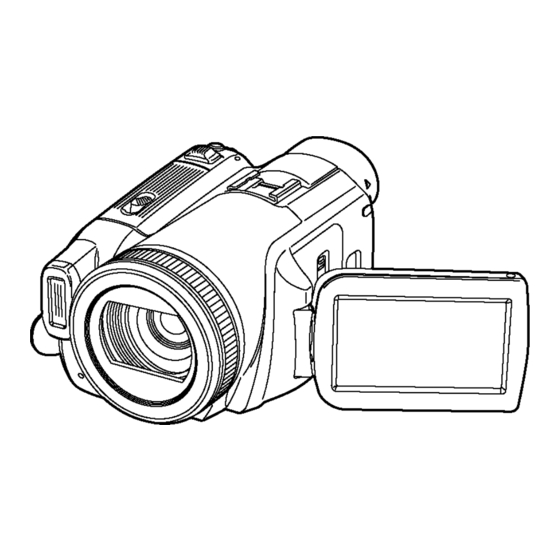
5 Location of Controls and Components Followings are the Location of Controls and Components for NV-GS500EB as a sample. For other models, refer to each Operatin Instructions. -
Page 12: Service Mode
6 Service Mode 6.1. Error Display is displayed automatically on the EVF or the LCD Monitor when an undesirable condition has occured. -
Page 13: Service Menu
6.2. Service Menu When abnormal detection contents are confirmed a When I do the following operation automatic diagnosis cord is dis- played. 1. Preparation Remove the card and tape from this machine. 2. Service menu is dieplayed. (see Fig. S1) Pushed [PHOTO SHOT] button and [JOYSTICK LEFT ] button and [AUTO/MANUAL/FOCUS switch to FOCUS] button simmultaneously for 3 seconds. - Page 14 Display contents (self diagnosis cord contents) Turn off the power supply after confirmation. Please do the error cord backup record the clear after repair completion. CLEAR METHOD If the Card and Tape inserted, take out it before Service Mode operation. Making the mode dial of This Machine a tape recording mode, push [JOYSTICK LEFT ] button and [AUTO/MANUAL/FOCUS switch to FOCUS] button and [RECORDING START/STOP] button simultaneously for 3 seconds.
-
Page 15: Service Fixture & Tools
7 Service Fixture & Tools 7.1. Service Tools and Equipment Parts Name Parts No. Q'ty Remarks Step Up Ring VFK1164TAR43 For Collimator 43mm TATSUJIN PC-Adjustment Program VF0D2003AV30 Envelope Detection Special Board VFK1641 Post Driver VFK1899 Standard Tape VFM3010EDS Extension Cable (45pin) VFK1575C4520 FP6902 (Main) - FP4801 (Front) -
Page 16: Disassembly And Assembly Instructions
8 Disassembly and Assembly Instructions 8.1. Disassembly Frow Chart This flow chart indicates the disassembly steps the cabinet parts, P.C.B. and Mecha. Unit in order to access to be serviced. When reinstalling, perform the steps in the reverse order. 8.2. P.C.B. -
Page 17: Disassembly Procedures
8.3. Disassembly Procedures Item / Part Fig. Removal (Screw,Connector,Flex. & Other) Flow-Chart for Disassembly Procedure 12 Monitor P.C.B. Fig.D25 2-Screws (e), 2-Screws (f) LCD Case (Upper) Unit Fig.D26 1-Connector FP902 Item / Part Fig. Removal LCD Hinge Unit, LCD Earth Plate (Screw,Connector,Flex. - Page 18 Fig. D2 Fig. D4 Fig. D5 Fig. D3...
- Page 19 Fig. D6 Fig. D8 Fig. D7 Fig. D9...
- Page 20 Fig. D10 Fig. D12 Fig. D11 Fig. D13...
- Page 21 Fig. D16 Fig. D14 Fig. D15 Fig. D17...
- Page 22 Fig. D18 Fig. D19...
- Page 23 Fig. D22 Fig. D20 Fig. D23 Fig. D21...
- Page 24 Fig. D26 Fig. D24 Fig. D27 Fig. D25...
- Page 25 Fig. D28 Fig. D30 Fig. D31 Fig. D29...
- Page 26 Fig. D32...
-
Page 27: Disassembly Procedures Mecha. Unit
8.4. Disassembly Procedures Mecha. Unit Flow-Chart for Disassembly Procedure Item / Part Fig. Removal (Screw, Connector, Flex. & Other) Cassette Up Unit Fig. M1 It makes the mechanism position in Eject condition (For Battery) Fig. M2 3-Screws (A) Fig. M3 3-Tabs I remove the piece arrangement unit from rail department Cylinder Unit Fig. - Page 28 Fig. M3...
- Page 29 Fig. M4 Fig. M5...
- Page 30 Fig. M6...
-
Page 31: Disassembly Procedures Of Camera Lens Unit
8.5. Disassembly Procedures of Camera Lens Unit The following flowchart describes order or steps for removing the Camera lens unit and certain printed circuit boards in order to make access to the item needing service. To reassemble the unit follow the steps in reverse order. Fig. -
Page 32: Measurements And Adjustments
9 Measurements and Adjustments 9.1. Service Positions 9.1.1. List of the extension cables Use the following extension cables when checking or adjusting individual circuit boards except module Parts. (Main P.C.B. and Sub P.C.B.) - Page 33 9.1.2. Checking and repairing individual circuit boards except module parts (Main P.C.B. and Sub P.C.B.) How to use extension cables.
-
Page 34: Location For Connectors Of The Main P.c.b. & Sub P.c.b
9.2. Location for Connectors of the Main P.C.B. & Sub P.C.B. 9.2.1. Main P.C.B. PS6901 K1KB60A00157 FP1001 K1MN18AA0018 IC2002 (EEPROM/RTS) PS3001 K1KBA0A00097 FP2202 K1MN10BA0197 FP6903 FP2204 FP2201 PP3001 K1MN21BA0132 K1MN08BA0197 K1MN18BA0197 K1KA20BA0052 (COMPONENT SIDE) FP5001 FP2203 K1MN08BA0107 K1MN18BA0060 (FOIL SIDE) - Page 35 9.2.2. Sub P.C.B. PS201 K1KB40A00058 FP701 K1MN45B00033 (COMPONENT SIDE) PP301 K1KAA0A00111 IC307 (EEPROM) (FOIL SIDE)
-
Page 36: Electrical Adjustment Procedures
9.3. Electrical Adjustment Procedures 9.3.1. Computer assisted adjustment system <TATSUJIN> adjustment This unit employs the computer assisted system named; for Electrical adjustment. It is required to install a USB driver for service which can be download only from TSN-WEB. 9.3.2. Set-up manual for DV-Camcorder. - Page 37 Fig. E2 Rough image of set-up connection...
- Page 38 9.3.3. Set up PC-EVR adjustment program 1. Turn on the PC and install the TATSUJIN Adjustment Pro- 6. Saving for EEPROM data is complete, menu will appear. gram into the PC. To perform each adjustment, display the adjustment 2. TATSUJIN PC-Adjustment Program start in the following menu by selecting the desired menu from procedure.
-
Page 39: Initial Guideline
9.3.4. Initial guideline The table below shows which adjustments are necessary according to the unit parts and individual parts to be replaced. Make sure to perform these adjustments shown below as necessary. -
Page 40: Mechanical Adjustment Procedures
9.4. Mechanical Adjustment Procedures 9.4.1. Adjustment item Item Adjustment at the time of the part exchange Half finished goods mechanism Clyinder Remarks Linearlty adjustment & BER value confirmation 9.4.2. Adjustment procedures Pay attention, because the adjustment method is different from this machine. lLinearlty adjustment &... - Page 41 Fig. D2 Fig. D3 Fig. D4...
-
Page 42: Maintenace
10 Maintenace 10.1. Cleaning Lens, Viewfinder and LCD Panel Do not touch the surface of lens, Viewfinder and LCD Panel with your hand. When cleaning the lens, use air-Blower to blow off the dust. When cleaning the LCD Panel, dampen the lens cleaning paper with lens cleaner, and the gently wipe the their surface. Note: A lens cleaning paper and lens cleaner are available at local camera shops and market place. - Page 43 "Standard-Playback" mode when there is no specify mode is mentioned. 4.Although the voltage and waveform available on here is measured with standard frame, NV-GS500EG NV-GS500GN it may be differ from actual measurement due to modification of circuit and so on.
-
Page 44: S2. Voltage And Waveform Chart
S2. Voltage and Waveform Chart Note) Indicated voltage values are the standard values for the unit measured by the DC electronic circuit tester (high-impedance) with the chassis taken as standard. Therefore, there may exist some errors in the voltage values, depending on the internal impedance of the DC circuit tester. S2.1. -
Page 45: S3. Block Diagram
S3. Block Diagram S3.1. Overall Block Diagram LENS UNIT EXT MIC/ AV MULTI JACK FREE STYLE SPEAKER MMC/SD REMOTE TERMINAL (AV/S OUTPUT) CONTROL ZOOM IRIS FOCUS FLASH IC7003,T7001 IC4801 IC3301 AVIO (FLASH DRIVE) (MIC AMP) (D/A,A/D,AV OUT AMP) AVIO IC101 (CG/SSG/V DRIVER) IC841,842 (GYRO) -
Page 46: S4. Schematic Diagram
S4. Schematic Diagram S4.1. Interconnection Diagram S4.1.1. Interconnection Diagram (1) CL4801 ECM(R) LENS UNIT FP7002 CL4802 KCENON(A) CL4803 KCENON(A) KCENON(A) ECM(L) KCENON(A) KCENON(A) FP4801 KCENON(A) ST_NOREG MIC UNIT ST_NOREG ST_NOREG AV_GND AV_GND TRIGEND TRIG CHARGE TRIG CHAEND FLASH ROUT LOUT GNDG ATFI GNDG... -
Page 47: S4.1.2. Interconnection Diagram (2
S4.1.2. Interconnection Diagram (2) S601 LCD RVS SWITCH RESET FP602 FP902 FP903 M_RVS DGND COM1 POWER LCD DGND DGND DGND DGND DGND M_PWM AUTO/MANUAL/MF LCD OPEN SWITCH M_PWM M_LED5V CL6301 M_LED5V M_COM_COMAC CL6302 M_COM_COMAC M_STV M_STV M_CKV LCD DET P.C.B. M_CKV M_OEV_ENB NRW2... -
Page 48: S4.2. Side-R Schematic Diagram
S4.2. Side-R Schematic Diagram NV-GS500/GS508 Series Side-R Section (Side-R P.C.B. (1/2)) Schematic Diagram... -
Page 49: S4.3. Lcd Schematic Diagram
S4.3. LCD Schematic Diagram NV-GS500/GS508 Series LCD Section (Side-R P.C.B. (2/2)) Schematic Diagram... -
Page 50: S4.4. Lcd Det Schematic Diagram
S4.4. LCD Det Schematic Diagram / S4.5. Operation (R) Schematic Diagram NV-GS500/GS508 Series NV-GS500/GS508 Series LCD Det Operation (R) Schematic Diagram Schematic Diagram... -
Page 51: S4.6. Evf Schematic Diagram
S4.6. EVF Schematic Diagram NV-GS500/GS508 Series Schematic Diagram... -
Page 52: S4.7. Front Schematic Diagram
S4.7. Front Schematic Diagram NV-GS500/GS508 Series Front Schematic Diagram S-10... - Page 53 NV-GS500/GS508 Series Front Schematic Diagram S-11 S-11...
- Page 54 NV-GS500/GS508 Series Front Schematic Diagram S-12...
- Page 55 NV-GS500/GS508 Series Front Schematic Diagram S-13...
-
Page 56: S4.8. Side-L Schematic Diagram
S4.8. Side-L Schematic Diagram NV-GS500/GS508 Series Side-L Schematic Diagram S-14... -
Page 57: S4.9. Monitor Schematic Diagram
S4.9. Monitor Schematic Diagram NV-GS500/GS508 Series Monitor Schematic Diagram S-15... -
Page 58: S4.10. Ccd Schematic Diagram
S4.10. CCD Schematic Diagram NV-GS500/GS508 Series Schematic Diagram S-16 S-16... - Page 59 NV-GS500/GS508 Series Schematic Diagram S-17...
- Page 60 NV-GS500/GS508 Series Schematic Diagram S-18...
- Page 61 NV-GS500/GS508 Series Schematic Diagram S-19...
-
Page 62: S5. Print Circuit Board
S5. Print Circuit Board S5.1. Side-R P.C.B. S5.1.1. Side-R P.C.B. (Component Side) (Component Side) NV-GS500/GS508 Series Side-R P.C.B. (Component Side) S-20... -
Page 63: S5.1.2. Side-R P.c.b. (Foil Side
S5.1.2. Side-R P.C.B. (Foil Side) (Foil Side) NV-GS500/GS508 Series Side-R P.C.B. (Foil Side) S-21... -
Page 64: S5.2. Lcd Det P.c.b
S5.2. LCD Det P.C.B. / S5.3. Operation (R) P.C.B. / S5.4. EVF P.C.B. (Component Side) (Component Side) (Foil Side) (Foil Side) NV-GS500/GS508 Series NV-GS500/GS508 Series NV-GS500/GS508 Series LCD Det P.C.B. Operation (R) P.C.B. EVF P.C.B. S-22... - Page 65 S-23...
-
Page 66: S5.5. Front P.c.b
S5.5. Front P.C.B. NV-GS500/GS508 Series Front P.C.B. (Component Side) S-24 S-24... - Page 67 NV-GS500/GS508 Series Front P.C.B. (Foil Side) S-25...
- Page 68 (Component Side) NV-GS500/GS508 Series Front P.C.B. (Component Side) S-26...
- Page 69 (Foil Side) NV-GS500/GS508 Series Front P.C.B. (Foil Side) S-27...
-
Page 70: S5.6. Side-L P.c.b
S5.6. Side-L P.C.B. (Foil Side) (Component Side) NV-GS500/GS508 Series Side-L P.C.B. S-28... -
Page 71: S5.7. Monitor P.c.b
S5.7. Monitor P.C.B. S5.7.1. Monitor P.C.B. (Component Side) (Component Side) NV-GS500/GS508 Series Monitor P.C.B. (Component Side) S-29... -
Page 72: S5.7.2. Monitor P.c.b. (Foil Side
S5.7.2. Monitor P.C.B. (Foil Side) (Foil Side) NV-GS500/GS508 Series Monitor P.C.B. (Foil Side) S-30... -
Page 73: S5.8. Ccd Flex
S5.8. CCD Flex (Component Side) (Foil Side) NV-GS500/GS508 Series CCD Flex S-31... - Page 74 S-32...
-
Page 75: S6. Replacement Parts List
S6. Replacement Parts List Note: 1.* Be sure to make your orders of replacement parts according to this list. 2. IMPORTANT SAFETY NOTICE Components identified with the mark have the special characteristics for safety. When replacing any of these components, use only the same type. 3. - Page 76 NV-GS500EG/EB/EP/EE/E/GC/GN/SG/GCT/PL/GT, GS508GK vol.1 Ref.No. Part No. Part Name & Description Remarks Ref.No. Part No. Part Name & Description Remarks C614 F1H0J2250003 C.CAPACITOR CH 6.3V 2.2U VEP22365A CCD FPC (RTL) C616 F1G0J105A001 C.CAPACITOR CH 6.3V 1U C624 ECJ0EB1A104K C.CAPACITOR CH 10V 0.1U C201 ECJ0EB1A104K C.CAPACITOR CH 10V 0.1U...
- Page 77 NV-GS500EG/EB/EP/EE/E/GC/GN/SG/GCT/PL/GT, GS508GK vol.1 Ref.No. Part No. Part Name & Description Remarks Ref.No. Part No. Part Name & Description Remarks R634 D0YAR0000007 M.RESISTOR CH 1/16W FP902 K1MN23BA0132 CONNECTOR R6301 ERJ6GEYJR47 M.RESISTOR CH 1/10W 0.47 FP903 K1MN24BA0055 CONNECTOR R6302 ERJ2GEJ150 M.RESISTOR CH 1/16W 15...
- Page 78 NV-GS500EG/EB/EP/EE/E/GC/GN/SG/GCT/PL/GT, GS508GK vol.1 Ref.No. Part No. Part Name & Description Remarks Ref.No. Part No. Part Name & Description Remarks LB4922 J0JBC0000107 FILTER LB4923 J0JBC0000107 FILTER VEP04899B FRONT P.C.B. (RTL) LB4924 J0JBC0000107 FILTER LB4926 J0JBC0000107 FILTER C481 F3F0J226A057 E.CAPACITOR CH 6.3V 22U...
- Page 79 NV-GS500EG/EB/EP/EE/E/GC/GN/SG/GCT/PL/GT, GS508GK vol.1 Ref.No. Part No. Part Name & Description Remarks Ref.No. Part No. Part Name & Description Remarks R7008 ERJ2GEJ101 M.RESISTOR CH 1/16W 100 R7009 ERJ2GEJ103 M.RESISTOR CH 1/16W 10K R7010 ERJ2GEJ222 M.RESISTOR CH 1/16W 2.2K R7011 ERJ2GEJ104 M.RESISTOR CH 1/16W 100K...
- Page 80 NV-GS500EG/EB/EP/EE/E/GC/GN/SG/GCT/PL/GT, GS508GK vol.1 Ref.No. Part No. Part Name & Description Remarks Ref.No. Part No. Part Name & Description Remarks XQN16+BJ8FN SCREW VYK1U37 SIDE CASE (R) 3 UNIT XQS2+A25FN SCREW VGL1163 SD PANEL LIGHT XQS2+A25FN SCREW VGQ8659 KNOB HOLDER XQN16+BJ6FN SCREW...
- Page 81 NV-GS500EG/EB/EP/EE/E/GC/GN/SG/GCT/PL/GT, GS508GK vol.1 Ref.No. Part No. Part Name & Description Remarks Ref.No. Part No. Part Name & Description Remarks N9ZZ00000322 GRIP OPERATING UNIT VKM6897 LCD CASE (T) 1 (EXCEPT GK-S) VML3927 CASSETTE LOCK LEVER VKM6898 LCD CASE (T) 1 GK...
- Page 82 NV-GS500EG/EB/EP/EE/E/GC/GN/SG/GCT/PL/GT, GS508GK vol.1 Ref.No. Part No. Part Name & Description Remarks Ref.No. Part No. Part Name & Description Remarks VXQ1403 PRISM (1) VXA8276 MECHANISM CHASSIS VXW0774 LENS UNIT 501-1 VXA8198 CASSETTE UP UNIT 302-1 VXQ1231 MASTER FLANGE 501-1-1 VMB3766 CASSETTE UP SPRING...
- Page 83 NV-GS500EG/EB/EP/EE/E/GC/GN/SG/GCT/PL/GT, GS508GK vol.1 Ref.No. Part No. Part Name & Description Remarks Ref.No. Part No. Part Name & Description Remarks VPG1F06 PACKING CASE 1 (EXCEPT GK) VPG1F07 PACKING CASE 1 GK VPN6367 CUSHION VPK2942 ACCESSORIES BOX K2GJ2DZ00018 DC CABLE K2KZ9CB00001 AV CABLE ...
-
Page 84: S7. Exploded View
S7. Exploded View S7.1. Frame and Casing Section (1) 26 (RTL) EVF B/C P.C.B. 12 (RTL) 10 (RTL) OPERATION (R) P.C.B. LCD DET. P.C.B. 49 (RTL) FRONT P.C.B. 9 (RTL) SIDE-R P.C.B. 49-5 49-1 49-3 49-2 49-4 (RTL) ECM P.C.B. S-42... -
Page 85: S7.2. Frame And Casing Section (2
S7.2. Frame and Casing Section (2) B111 B120 B125 B119 B103 105 (RTL) SIDE (L) P.C.B. B101 B113 B106 B105 B104 B112 B127 B109 B108 B117 B110 123 (RTL) MAIN P.C.B. B107 B116 123-1 B115 B118 B102 B123 124 (RTL) SUB P.C.B. -
Page 86: S7.3. Lcd Section
S7.3. LCD Section 211 (RTL) MONITOR P.C.B. B203 B201 B204 B202 S-44... -
Page 87: S7.4. Camera Lens Section
S7.4. Camera Lens Section B301 B302 302-1 302-6 B304 302-2 302-7 302-13 302-3 302-4 302-8 302-5 B310 B309 B305 302-9 302-10 302-14 302-11 B306 B307 B311 B308 302-12 B312 B313 S-45... -
Page 88: S7.5. Video Mechanism Section
S7.5. Video Mechanism Section 501-1 B501 501-1-1 B507 501-2 B506 B505 B504 B502 B503 S-46... -
Page 89: S7.6. Packing Parts And Accessories Section
S7.6. Packing Parts and Accessories Section (NV-GS500GN) (NV-GS500EB/GC/SG/GCT) (NV-GS500EG/EP/EE/E/GC/SG) (NV-GS500PL/GT,GS508GK) Head Cleaner (NV-GS500EE/GC/GN/GCT/ SG,GS508GK) Battery Pack Unit Button-Type Battery S-47...
Need help?
Do you have a question about the NV-GS500EG and is the answer not in the manual?
Questions and answers