Table of Contents

Summary of Contents for Ironton Arc 200
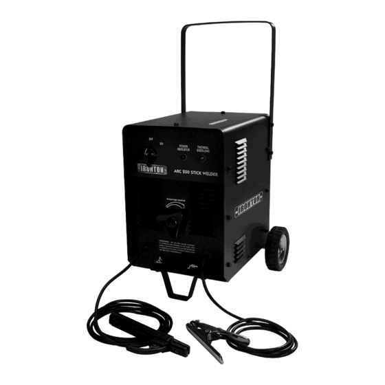
- Page 1 Arc 200 OWNER’S MANUAL WARNING: Read carefully and understand all ASSEMBLY AND OPERATION INSTRUCTIONS before operating. Failure to follow the safety rules and other basic safety precautions may result in serious personal injury. Item# 45432...
-
Page 2: Intended Use
For technical questions please call the Northern Tool Welder Help Line at 1-877-304-0294. INTENDED USE The ARC 200 is a AC only stick welder. It is intended for use for welding steel, stainless steel, cast iron and hard surfacing using electrodes from 1/16 inch to 5/32 inch. For best performance on steel, we highly recommend an 1/8 inch 6013 electrode. -
Page 3: General Safety Rules
CAUTION: Do not allow persons to operate or assemble this Arc 200 until they have read this manual and have developed a thorough understanding of how the Arc 200 works. WARNING: The warnings, cautions, and instructions discussed in this instruction manual cannot cover all possible conditions or situations that could occur. - Page 4 1.3 Use of Your Welder Do not operate the welder if the output cable, electrode, torch, wire or wire feed system is wet. Do not immerse them in water. These components and the welder must be completely dry before attempting to use them. -Follow the instructions in this manual.
- Page 5 Fumes and Gases -Fumes emitted from the welding process displace clean air and can result in injury or death. -Do not breathe in fumes emitted by the welding process. Make sure your breathing air is clean and safe. -Work only in a well-ventilated area or use a ventilation device to remove welding fumes from the environment where you will be working.
- Page 6 Hot Materials Welded materials are hot and can cause severe burns if handled improperly. -Do not touch welded materials with bare hands. -Do not touch MIG gun nozzle after welding until it has had time to cool down. Sparks/Flying Debris Welding creates hot sparks that can cause injury.
-
Page 7: Technical Specifications
Arc 200 operation. Replace or repair damaged or worn parts immediately. Store idle Arc 200. When Arc 200 is not in use, store it in a secure place out of the reach of children. Inspect it for good working condition prior to storage and before re-use. - Page 8 ON/OFF Switch In the “OFF” position no power is being supplied to the electrode holder. In the “ON” position power is supplied to the main transformer and control circuit. Indicator Lights There are two indicator lights: 1) Power and 2) Thermal Overload. When the machine is turned on, the power indicator will be on.
- Page 9 2.2. Install the axle tube/bracket for the axles and wheels on the axle. See following image. Stand the machine up and install the axle tube/bracket onto the back of panel using the screws and washers provided. (You may want to use a wooded block to hold the welder up for this step.) 2.3.
-
Page 10: Installation
INSTALLATION 1. POWER REQUIREMENT - AC single phase 230V, 60 HZ with a 50 amp circuit breaker is required. DO NOT OPERATE THIS UNIT if the ACTUAL power source voltage is less than 207 volts AC or greater than 253 volts AC. ... -
Page 11: Ground Clamp Connection
Based on different welding position, there are different welding joint, see following images for more information. 4. GROUND CLAMP CONNECTION Clear any dirt, rust, scale, oil or paint on the ground clamp. Make certain you have a good solid ground connection. A poor connection at the ground clamp will waste power and heat. Make sure the ground clamp touches the metal. - Page 12 6. SELECTING THE PROPER ELECTRODE There is no golden rule that determine the exact rod or heat setting required for every situation. The type and thickness of metal and the position of the work piece determine the electrode type and the amount of heat needed in the welding process.
-
Page 13: Welding Techniques
8. WELDING TECHNIQUES The best way to teach yourself how to weld is with short periods of practice at regular intervals. All practice welds should be done on scrap metal that can be discarded. Do not attempt to make any repairs on valuable equipment until you have satisfied yourself that your practice welds are of good appearance and free of slag or gas inclusions. - Page 14 8.3 Types of weld bead The following paragraphs discuss the most commonly used arc welding beads. The stringer bead Formed by traveling with the electrode in a straight line while keeping the electrode centered over the weld joint. Stringer Bead Weave Bead The weave bead Used when you want to deposit metal over a wider space than would be possible with a stringer bead.
-
Page 15: Maintenance
Maintain your IRONTON Arc 200. It is recommended that the general condition of any IRONTON Arc 200 be examined before it is used. Keep your IRONTON Arc 200 in good repair by adopting a program of conscientious repair and maintenance. Have necessary repairs made by qualified service personnel. -
Page 16: Troubleshooting
TROUBLESHOOTING SYMPTOM POSSIBLE CAUSE CORRECTIVE ACTION Unit Does Not Power Up Unit Is Not Plugged In Plug In Unit Input Power Circuit Breaker Not On Reset Input Power Circuit Breaker The Main Power Switch Is Not Working Replace Main Power Switch Can Not Create An Arc Work Piece is Painted Or Rusty Remove All Paint And Rust... -
Page 17: Diagram & Parts List
DIAGRAM & PARTS LIST Page of 19... - Page 18 Reference # Part# Description Qty. 1.1.01.05.0010 HANDLE 2.05.18.007 INDEX PANEL 1.1.01.01.0066 ENCLOSURE 1.1.02.03.0391 TRANSFORMER 2.06.29.051 CLIP CLUTH 2.07.36.739 THERMO-RELAY 1.1.02.03.0003 MOVABLE IRON CORE 2.01.29.052 MOVABLE IRON CORE SUPPORTER 2.06.29.221 SPRING 2.01.29.920 AMPERAGE INDICATOR 2.04.31.205 RUBBER RING 2.05.08.002 AMPERAGE ADJUSTMENT KNOB 1.2.07.02.0009 INDICATOR LIGHT WIRING 2.07.80.721...
-
Page 19: Warranty
WARRANTY EFFECTIVE JULY 1, 2014 LIMITED WARRANTY This warranty applies to the original purchaser and is subject to the terms and conditions listed below. This Limited Warranty is for new equipment sold after the above date, providing coverage for defects in material and workmanship at the time it is shipped from the factory.
Need help?
Do you have a question about the Arc 200 and is the answer not in the manual?
Questions and answers