Table of Contents
Advertisement
Advertisement
Table of Contents

Subscribe to Our Youtube Channel
Summary of Contents for Liquid Controls LectroCount
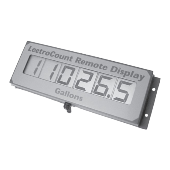
- Page 1 Installation & Parts Manual LectroCount Remote Display ® Installation: EM100-13...
-
Page 2: Table Of Contents
Decimal Point Jumper Setting ....8 Publication Updates and Translations The most current English versions of all Liquid Controls publications are available on our website, www.lcmeter.com. It is the responsibility of the Local Distributor to provide the most current version of LC Manuals, Instructions, and Specification Sheets in the required language of the country, or the language of the end user to which the products are shipping . -
Page 3: Specifications
Specifications The LectroCount Remote Display is a 6-digit, backlit display with 2¼" high digits, viewable to 100 ft, for flow metering applications. LectroCount Remote Display models are available for LectroCount LCR , LectroCount LCR-II and LectroCount³ ® ® Electronic Registers. -
Page 4: Installation
Installation ! ! ! ! ! CAUTION The LectroCount Remote Display and accessories (whether supplied by Liquid Controls or other) must be installed and operated in accordance with all applicable federal, state, and local construction, electrical, environmental and safety codes. Failure to do so could result in serious injury or death. -
Page 5: Mounting Dimensions
The diagram below shows the overall dimensions and using the four holes provided in the rear cover. The hole the locations of the mounting holes on the LectroCount size is designed for use with ¼" screws. It is important Remote Display. -
Page 6: Optimum Viewing Angle
The horizontal, perpendicular by a specified amount. The Liquid Controls side to side viewing angle is 40º left and right from center. LectroCount Remote Display is designed with a bias set Figure 5. Optimum Viewing Angle... -
Page 7: Remote Display Shield Accessory
Use the optional shield to reduce the effect of glare. This shield fits in place over the LectroCount Remote Display as shown in Figure 6. The holes in the shield are slotted for ease of installation. -
Page 8: Decimal Point Jumper Setting
Once the enclosure is opened, the jumpers may be moved decimal configuration appearing on the LectroCount to configure the display according to the LectroCount LCR-II display. There is no need to adjust the jumpers Electronic Register for which it is designed. See the table on Model E1610. -
Page 9: Wiring Diagrams
Route the 30 foot cable provided Figure 11. Select Switch Wiring Diagram to the LectroCount LCR-II and connect the cord grip to an available port on the back of the LCR-II. Route the free end of the 30 foot cable through the cord grip on the back of the LCR-II. -
Page 10: Lectrocount Lcr
LC³ and connect the cord grip provided. Route the cable through the cord grip and connect the cable to the J1 Connector on the LectroCount³ PCB as shown in Figure 13. J1 (LC³) J1 (Remote Display) -
Page 11: Dual Display Kit
3. Remove the cord grip and cable from the unit. Electronic Register as shown on Pages 9-10. 4. Install the 4-Port Junction Box in the space where the cord grip was just removed. Figure 14. Dual Display Kit - 2 Remote Displays with 1 LectroCount Electronic Register... -
Page 12: Illustrated Parts Breakdown
Illustrated Parts Breakdown A Unit of IDEX Corporation 105 Albrecht Drive Lake Bluff, IL 60044-2242 • 1.800.458.5262 847.295.1050 © 2007 Liquid Controls Fax: 847.295.1057 Pub. No. 500316 www.lcmeter.com (07/20/07)
Need help?
Do you have a question about the LectroCount and is the answer not in the manual?
Questions and answers