Asus Eee PC 4G Service Overview
Asus eee pc 4g service overview
Hide thumbs
Also See for Eee PC 4G:
- User manual (78 pages) ,
- Quick use manual (15 pages) ,
- A 'how to' manual (2 pages)
Table of Contents
Advertisement
Service Overview
Carefully read through this chapter for a look at various components of
the Eee PC 4G (701) and necessary cautions and tools before performing
any service and repairs.
T
o provide the best service and support for the ASUS Eee PC 4G (701), we have
provided the below information for technicians from distributors and resellers to
perform the complete disassembly and assembly. But before performing the procedures,
please be sure to read through the overview in this chapter for component overview,
cautions and tools to avoid any unwarranted damages to the hardware.
The following chapter includes:
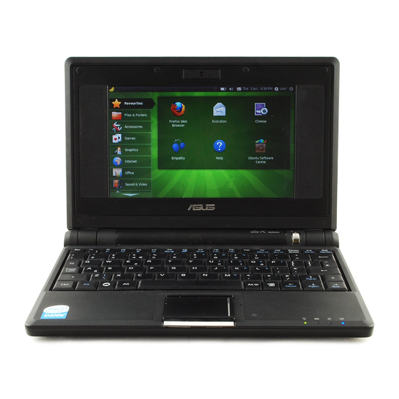
• Eee PC 4G (701) Overview
• Components
• Precautions
• Appropriate Tools
Service overview
1-1
1
Chapter
Advertisement
Table of Contents

Related Manuals for Asus Eee PC 4G


Summary of Contents for Asus Eee PC 4G
- Page 1 Eee PC 4G (701) and necessary cautions and tools before performing any service and repairs. o provide the best service and support for the ASUS Eee PC 4G (701), we have provided the below information for technicians from distributors and resellers to perform the complete disassembly and assembly.
- Page 2 Service overview Eee PC 4G (701) Overview and Components The ASUS Eee PC 4G (701) is a product combining the power of Intel® Mobile Processor. In this section, an overview for the Eee PC 4G (701), along with its components, will be presented.
- Page 3 Service overview LAN port USB (2.0) ports SPDIF/Headphone Microphone port Modem port Air Vents USB (2.0) ports VGA port Card reader Kensington Lock Front view Battery Pack DC-IN 1 - 3...
- Page 4 The illustrations below show the components of the Eee PC 4G (701). LCD Panel L C D The illustration below shows the LCD display panel. The Eee PC 4G (701) comes with 7” TFT LCD Panel. Inverter Board I N V E R T E R The illustration below shows the inverter board, which is hidden underneath the lower edge of the LCD front bezel.
- Page 5 The illustration below shows the keyboard plate. It can be exchanged with keyboard plates with different language layouts, such as U.S., France and others. Top Case Module T O P C A S E & The illustration below shows the top case of the Eee PC 4G (701). 1 - 5...
- Page 6 The illustration below shows the Touch Pad module, top and bottom view. Battery Pack B A T T E R Y The illustration below shows the battery packs of the Eee PC 4G (701). It’s located at bottom of the EEE PC 4G (701). Memory Module M E M O R Y The illustration below shows the memory module for the Eee PC 4G (701).
- Page 7 M O D U L E Bottom Case Module B O T T O M C A S E The illustration below shows the bottom case module of the Eee PC 4G (701), top and bottom view. Wireless LAN Module W I R E L E S S The illustration below shows the Wireless LAN Module of the Eee PC 4G (701).
- Page 8 Service overview Service Overview Please pay special attention to the cautions below to prevent any damages to the Eee PC 4G (701) and also please be sure to select the appropriate tools described in this section to perform any services desired.
- Page 9 Service overview 5. Always wear a ground strap on your hand to protect the Eee PC 4G (701) from static discharge. Appropriate Tools T O O L S The illustrations below show the appropriate tools that should be used for the Eee PC 4G (701)’s service and repair.
- Page 10 Disassembly Cautions D I S A S S E M B L Y Before you perform any service and or repair on the Eee PC 4G (701), please read the notice C A U T I O N S below first.
-
Page 11: Disassembly Procedure
Disassembly Procedure Please follow the information provided in this section to perform the complete disassembly procedure of the Eee PC 4G (701). Be sure to use proper tools described before. SUS Eee PC 4G (701)consists of various modules. This chapter describes the procedures for the complete Eee PC 4G (701) disassembly. - Page 12 2.Slide the battery latch and hold the battery to remove it from system. M E M O R Y Memory Module The illustration shows how to remove the memory module form the Eee PC 4G (701). M O D U L E Removing Memory module 1.
-
Page 13: Removing Keyboard
Disassembly procedure 2. Softly open the two latches to pop the memory module up at 45 degree angles and then remove the memory at that angle. Keyboard Module K E Y B O A R D The illustration of below shows how to remove the keyboard Removing Keyboard M O D U L E 1. - Page 14 Disassembly procedure 2. Place the keyboard plate on the top case and disconnect the keyboard FPC to remove. Removing Keyboard Cable 1. Use a flexible connector tool to unlock the cable connector on both ends (no. 1). 2. Carefully pull out the keyboard cable (no. 2) with a pair of tweezers. 3.
- Page 15 Disassembly procedure 2. Close and turn the system upside down to remove 6 screws (M2*4) on the bottom case. 3. Softly pry the four sides of the system to open the latch hooks securing the top case with bottom case, then remove the top case. 2 - 5...
- Page 16 Disassembly procedure 4. Remove 1 piece of tape on the touch pad FPC then open the latch to disconnect it from touch pad board. 5. Remove 2 screws (M2*3) securing touch pad bracket and then remove the bracket. 6. Remove the touch pad board from the top case. 2 - 6...
-
Page 17: Wlan Module
Disassembly procedure WLAN Module W L A N The illustrations below show how to remove the WLAN module from the Eee PC 4G (701). M O D U L E Remove WLAN module W L A N 1. Remove 3 pieces of tape fixing the cable and then disconnect the following 4 cables, namely speaker cable, CMR cable, Fan cable, LVDS cable. - Page 18 Disassembly procedure 3. Lift the mother board from bottom case by softly separating from the bottom side, two sides to the top.* pay attention not to remove the mother board for now, for that the WLAN antenna is still connected with the mother board. 4.
- Page 19 Disassembly procedure 6. Remove 2 screws (M2*4) on the WLAN module to pop up the module at 30 degree angles and then remove it at that angle. Motherboard M O T H E R B O A R D The illustrations below show how to disassemble and remove the Motherboard. Removing Motherboard M O T H E R B O A R D 1.
- Page 20 Disassembly procedure 2. Remove two screws (M2*3) securing the Modem module and then remove it from the mother board. 3. Remove 2 screws screwing the LCD hinges and then take the LCD display away. 4. Remove 1 piece of tape and 3 screws (M*4) securing the Fan module and then take the Fan module away.
-
Page 21: Lcd Module
Disassembly procedure LCD Module L C D M O D U L E The illustrations below show how to remove and disassemble the LCD module. The module contains LCD panel, Inverter board, LCD bezel, LCD back cover. Disassembling LCD Module L C D M O D U L E 1. - Page 22 Disassembly procedure 4.Unscrew 4 (M2*4) screws securing the inverter board and then take the LCD panel together with the inverter board away from LCD back cover . 5. Disconnect the inverter cable, LCD FPC cable from inverter board and take the board away.
- Page 23 Disassembly procedure 6. Disconnect the coaxial cable from inverter board. 7. Tear off 1 piece of tape fixing camera cable and take the camera cable off cable guide. 8. Remove the camera board from LCD back cover and then take the whole module away. 2 - 13...
- Page 24 Disassembly procedure 9. Take the WLAN antennas off cable guides and remove the antennas together with its tape from LCD back cover. 10. Take the speaker cables off cable guides and remove both speakers from their slots. 2 - 14...
-
Page 25: Assembly Procedure
Assembly Procedure Please follow the information provided in this section to perform the complete assembly procedure of the Eee PC 4G (701). Be sure to use proper tools described before. fter you have completed the previous chapter of complete disassembly, please follow this chapter to assemble the Eee PC 4G (701) back together. - Page 26 Assembly procedure LCD Module L C D M O D U L E The illustrations below show how to assemble and install the LCD module of the Eee PC 4G (701). 1. Install the two speakers on LCD back cover and arrange the speaker cable well through cable guide.
- Page 27 Assembly procedure 3. Install the camera board on LCD back cover, pay attention to the aiming pole. 4. Connect the coaxial cable with inverter board. 5. Connect the inverter cable, LCD FPC cable with inverter board. 3 - 3...
- Page 28 Assembly procedure 6. Install the LCD panel together with the inverter board on LCD back cover and then secure 4 screws (M2*4) on it. 7. Assemble both hinges and secure 2 screws (M2*4) on each.*pay attention to differences between the left and right. 8.
- Page 29 Assembly procedure 9. Secure 6 screws (M2*4)on LCD front bezel and then fix 6 rubber pads on it. Motherboard M O T H E R B O A R D The illustrations below show how to assemble and install the motherboard of the Eee PC 4G (701).
- Page 30 Assembly procedure 3. Connect the Modem module with the mother board and then secure 2 scews (M2*3) . 4. Connect the Modem cable with the mother board and then arrange the cable to fix 2 pieces of tape on it. 3 - 6...
-
Page 31: Wireless Lan Module
The illustrations below show how to assemble and install the Wireless Lan Module of M O D U L E the Eee PC 4G (701). I N S T A L L A T I O N Installing Wireless LAN Module 1. - Page 32 Assembly procedure 3.Install the mother board on bottom case, to install you should first install the top side,then softly pry the two sides to the ports ends fit the bottom case well, finally press the bottom side to lock the latches.*make sure the antennas arrangeed through the hook at mother board, and all the cables placed above the mother board.
- Page 33 Assembly procedure 5. Connect the following cables and fix 3 pieces of tape on it. Speaker cable Camera cable Fan cable LVDS cable 3 - 9...
- Page 34 The illustrations below show how to assemble and install the top case module of the M O D U L E Eee PC 4G (701). 1. Install the touch pad board on top case. 2. Install the touch pad bracket and then secure 2 screws (M2*4) on it.
- Page 35 Assembly procedure 3. Connect touch pad FPC with touch pad board , fix the connector latch and then fix 1 piece of tape on it. 4. Install the top case with bottom case and press the four sides to make them fixed well. 5.
- Page 36 Assembly procedure 6. Connect the touch pad FPC and then secure 9 screws (M2*4) on it. Assembling Keyboard K E Y B O A R D The illustrations below show how to assemble and install the Keyboard of the Eee PC 4G (701).
- Page 37 Assembly procedure 2. Assemble the keyboard plate and press the 3 latches (F1; F6;Pause) in keyboard to lock it. Memory Module M E M O R Y The illustrations below show how to install the external Memory Module of the Eee PC M O D U L E 4G (701).
- Page 38 Assembly procedure Battery Module B A T T E R Y The illustrations below show how to install battery module of the Eee PC 4G (701). M O D U L E Install battery module. 1. Slide the battery module into its compartment 2.
- Page 39 Follow the individual procedures in this chapter to perform the Eee PC 4G (701)’s upgrade and replacement of various major components. sus Eee PC 4G (701) is a 2 spindles product, which means there are less options for you to upgrade and replacement. The key upgradeable and replaceable items include the Memory module.
-
Page 40: Memory Upgrade
Upgrade & replacement Memory Upgrade M E M O R Y Upgrading Memory Module Remove battery module 1.Slide the battery lock to open it 2.Slide the battery latch and hold the battery to remove it from system. Removing Memory module 1. - Page 41 Upgrade & replacement 2. Softly open the two latches to pop the Memory module up at 45 degree angles and then remove the Memory module at that angle. Installing Memory Module 1. Insert Memory at the same 45° angles and press down until it clicks into the latches. 2.
- Page 42 Upgrade & replacement Install battery module. 1. Slide the battery module into its compartment 2. Slide on the battery lock . 4 - 4...
-
Page 43: Hardware Specifications
Chapter Hardware Specifications You can enjoy and utilize the Eee PC 4G (701) Notebook more effectively with a better comprehension of detailed hardware specifications of the notebook. his chapter lists the detailed specifications of the notebook’s main system and modules. - Page 44 Hardware Technical Specification IST OF IGURES MARKETING SPEC Eee PC 4G (701) (One-Spindle Design) Specification Product Family EEE PC 4G (701) CPU Type Intel Celeron-M-ULV Dothan Speed 900MHz(normal run 630MHz) Package FCBGA 479 Onboard L2 Cache Size 512 KB On-die cache memory...
- Page 45 Hardware Technical Specification Flash ROM (SPI) SST/Winbond/MXIC 4Mbits Graphic Accelerator Intel 910GML internal GPU Controller Intel Internal graphic AGP Support Dual view/Dual App Graphic Memory Share Memory TV Out Support Sound System Controller Realtek ALC662 SW wave table FM synthesizer Speaker Stereo Azalia...
- Page 46 Hardware Technical Specification Controller Atheros L2 Internal Keyboard 80 Keys (W/ MS-Windows function keys) Function Key 12 Function Keys 13 Hot Keys Hot Key Function Suspend (STR or STD) Fn + F1 Wi-Fi enable Fn + F2 802.11b+g Application manager Fn + F6 Brightness Up Fn + F4...
- Page 47 Hardware Technical Specification Glide Pad Right Button Left Button Scroll Function Control Power On Button LCD Brightness Hot Keys LCD Lid Switch Sound Volume Hot Keys Password Override Yes (Master Password) Reset/Force Off Yes (Reset switch) I/O Port All ports support hot-plug Parallel 15-pin D-Sub Mouse/Keyboard...
- Page 48 Hardware Technical Specification 新力盛 1st Battery Charging time Li-ION (5200mAH) Machine ON TBD. Machine OFF TBD. Battery Life TBD. PM Off TBD. PM On TBD. Power Management AMI BIOS LCD Close/Open LCD Back-light Suspend/Resume Hibernation (S2D) Thermal Control ACPI DMI 2.0 Support DMI BIOS 2.1 Security Password...
- Page 49 Hardware Technical Specification CHIPSET LIST Chipset Summary Table Function EEE PC 4G (701) HW ACPI/PC99 Intel Dothan Not required SRAM (L2 Cache) 512KB Not required North Bridge Intel 910GML/910GMLE South Bridge Intel ICH6-M MEMORY DDR II SDRAM Not required BIOS ROM...
- Page 50 Hardware Technical Specification 2.1 CPU Processor Type: Intel Dothan Processor Intel Celeron-M ULV 353 Processor frequency: 900MHz (normal run 630MHz) Construction method: FCBGA479 Supply voltage: Core:0.85V(High_Frequency_Mode)~0.75V(lowest_Frequen cy_Mode) Function feature: On-die , primary 32-KB instruction cache and 32-KB write- back data cache. On-die , 512KB second level cache with Advanced Transfer Cache Architecture.
- Page 51 Hardware Technical Specification Vendor: Intel Parts Number: 910GML/910GMLE Package: 1257-ball micro-FCBGA 2.2.2 South Bridge Function: DMI x2/x4 interface link with GMCH Integrated PC/AT compatible system (DMA Controller, INT, Timer/Counters) Integrated channels controller with Ultra DMA/33/66/100 support Integrated USB 1.1 and 2.0 Host Bus controller with 8 USB ports Integrated HD Audio Interface Build-in RTC...
- Page 52 Hardware Technical Specification 2.3.2 EXPANSION MEMORY Number of sockets: One 200 pin SO-DIMM slot Bus: 64-bit data path Supply voltage: 1.8V Functional features: Supports up to 16 simultaneous open pages Hardware features: Supports DDR2 400 DDR devices Maximum of 2GB of system memory Parity support: without ECC 2.4 BIOS ROM...
- Page 53 Hardware Technical Specification 2.6 KEYBOARD CONTROLLER Function features: Embedded controller-style host Support hardware speed-up of GateA20 and RC Local 18x8 keyboard switch matrix support Three industry standard serial keyboard interfaces All three ports are bi-directional Vendor: Parts Number: KB3310 Package: 128-pin LQFP 2.7 AUDIO CODEC Vendor:...
- Page 54 Hardware Technical Specification 2.9 LAN & MODEM 2.9.1 LAN Function features: Scatter and gather transmit receive DMA Interrupt coalescing 10Mb/s, 100Mb/s, operation Compliant to ACPI 2.0 specification Compliant to IEEE 802.3u Auto-Negotiation Support Wake-on-LAN function and remote wake up (Magic Internal transmit and receive FIFO(2KB*2) Vendor: Atheros...
- Page 55 Hardware Technical Specification KEY PARTS LIST Key Parts Summary: 3.1 Display WVGA Technology: Active color (TFT: Thin Film Transistor) Size: 7”W Resolution: WVGA (800 X 480) Dimension: 164mm(H) * 103mm(V) * 5.1mm(T) Pixel Pitch: 0.1905mm * 0.1905mm Display Colors: 16M Colors Vendor: VGA+ Technology: Size:...
- Page 56 Hardware Technical Specification Vendor/Model Synaptics : SYNAPTICS/TM-01058-002 3.3 Keyboard Function Feature: Standard Notebook-Keyboard Hardware Feature: Simultaneously use of internal and external keyboard Easily to assemble or disassemble Compatibility: MS-Windows 2000/ XP Dimensions: 211.70 (H) x 80.70 (V) (Unit: mm) Type: Key switch membrane Total Travel: 1.5 +/- 0.2 (Unit: mm)
- Page 57 Hardware Technical Specification 3.4.2 RTC Backup Battery Purpose: Backup the RTC/CMOS data While AC adapter off & Main Battery removed Chemistry: Coin cell 2032 Li-ion battery Voltage: Nominal 3V Capacity: 200mAH Vendor: 3.5 AC/DC Adapter The notebook can be powered either by an external AC adapter or by an internal battery pack. The AC adapter is used as power source for the DC/DC converter and as constant current source for the battery pack.
- Page 58 Hardware Technical Specification SYSTEM 4.1 System diagram 4.2 Main components block diagrams 5-16...
- Page 59 Hardware Technical Specification 4.3 System resource 4.3.1 IRQ Map IRQ# Description IRQ 0 System Timer IRQ 1 PS2 Keyboard IRQ 8 System CMOS/RTC IRQ 9 ACPI IRQ Holder IRQ12 PS2 TP Numeric data processor IRQ13 IRQ14 Master IDE Controller IRQ15 Primary IDE Controller IRQ16 PCIE Root Port...
- Page 60 Hardware Technical Specification 4.3.3 PCI INT Map 4.3.4 PCI Bus Master Map 4.3.5 IDSEL 5-18...
- Page 61 Hardware Technical Specification I/O PORT PIN ASSIGNMENT FUNCTION DESCRIPTION Display (Analog) Flash module KEYBOARD TOUCHPAD&LED BATTERY .DC IN Adapter Input .AUDIO Headphone, Microphone-In .FAN .INVERTER .MDC .USB Universal Serial Bus LAN & Modem Universal Serial Bus .Card Reader . WLAN MINI PCIE 5-19...
- Page 62 Hardware Technical Specification 5.1 CRT Vendor Part No. Pin No. ALLTOP C10511-11505-B 15 Pin (DIP) Pin Assignment (by: sort) Description RED Video (analog) Red this DAC analog output drives the CRT interface. GREEN Video (analog) Green this DAC analog output drives the CRT interface.
- Page 63 Hardware Technical Specification 5.2 Flash module pin assignment Vendor Part No. Pin No. 52 Pin (DIP) Pin No. Pin No. Remark 1. IDE_DD0 2. IDE_DD15 3. IDE_DD1 4. GND 5. IDE_DD2 6. IDE_DD14 7. IDE_DD3 8. IDE_DD13 9. GND 10. IDE_DD12 11.
- Page 64 Hardware Technical Specification 5.3 LCD pin assignment Vendor Part No. Pin No. I-PEXV WTOB_CON_20P 20 Pin (SMD) Signal Description Type +3V_LCD LCD_CSB_D LCD_VSYNC LCD_SCL LCD_SDA LVDD_EN LA_DATAN0 LA_DATAP0 LA_DATAN1 LA_DATAP1 LA_DATAN2 LA_DATAP2 LA_CLKN LA_CLKP BL_PWM_DA BL_EN +12V_LEDIN 5-22...
- Page 65 Hardware Technical Specification 5.4 Internal keyboard pin assignment Vendor Part No. Pin No. InnovACE FPC_CON_28P 28 Pin (SMD) Signal Description Type KSO0 KSI0 KSO1 KSO2 KSI1 KSO3 KSI2 KSO4 KSI3 KSO5 KSI4 KSI5 KSO6 KSI6 KSI7 KSO7 KSO8 KSO9 KSO10 KSO11 KSO12 KSO1...
- Page 66 Hardware Technical Specification NC_KSO16 5.5 Internal Touch Pad & LED Pin assignment Vendor Part No. Pin No. ENTERY FPC_CON_12P 12 Pin (SMD) Signal Description Type Ground TP_L TP_L +5V_TP Power +5V_TP Power TP_DATA Data TP_DATA Data TP_CLK Clock Signal TP_CLK Clock Signal TP_R TP_R...
- Page 67 Hardware Technical Specification 5.6 1 Battery pin assignment Signal Description Type BAT_IN# Power BAT_ID Ground BAT_TS BAT_CONFIG Ground 5.7 DC in Jack pin assignment Vendor Part No. Pin No. SINGATRON DC_PWR_JACK_3P 3Pin (DIP) Signal Description Type A/D_DOCK_IN Adapter input voltage Ground Ground 5-25...
- Page 68 Hardware Technical Specification 5.8 Audio Jack 5.8.1 Internal Speaker Jack Vendor Part No. Pin No. ACES WtoB_CON_4P 4 Pin (SMD) Signal Description Type INTSPKR- Internal speaker signal right channel negative INTSPKR+ Internal speaker signal right channel positive INTSPKL- Internal speaker signal left channel negative INTSPKL+ Internal speaker signal left channel positive 5.8.2...
- Page 69 Hardware Technical Specification 5.8.3 Microphone Jack Vendor Part No. Pin No. SUYIN PHONE_JACK_6P 6 Pin (DIP) Signal Description Type GND_AUDIO Ground MIC1_JACK_L External microphone input MIC1_JACK_R External microphone input GND_AUDIO Ground MIC_SW# Control internal MIC 5.9 Fan Pin Assignment Vendor Part No.
- Page 70 Hardware Technical Specification None None Ground +3VAUX_MDC 3.3V power turned off during S4 ACZ_SYNC_MDC Azalia sync signal Ground ACZ_SDIN1_MD Azalia data input signal Ground ACZ_RST#_MDC Azalia reset signal ACZ_BCLK_MDC Azalia bit clock signal 5.11 USB pin assignment Vendor Part No. Pin No.
- Page 71 Hardware Technical Specification SUYIN USB_CON_1X4P 4 Pin (SMD) Signal Description Type +5V_USB34_CON USB 5V power USBPN3 USB port 3 negative signal USBPP3 USB port 3 positive signal USB 5V ground 5.12 LAN & Modem pin assignment Vendor Part No. Pin No. ALLTOP MODULAR_JACK_12P 12 Pin (SMD)
- Page 72 Hardware Technical Specification 5.13 Card Reader pin assignment Vendor Part No. Pin No. PANASONIC SD_SOCKET_9P 9 Pin (SMD) Pin No Signal Remark UB_SD_DATA3 UB_SD_CMD +3V_SD UB_SD_CLK UB_SD_DATA0 UB_SD_DATA1 UB_SD_DATA2 5-30...
- Page 73 Hardware Technical Specification POWER MANAGEMENT 6.1 System power plane Power Group Power Control Controlled Devices +12V VSUS_ON Other Control SUSB_ON LCD, Flash, Flash & Wlan LED, Fan, Camera, Codec, Audio, SB SUSB_ON NB IO, SB, LCD, Card reader, Codec, Audio +1.8V_DUAL SUSC_ON NB, DDR2 power...
- Page 74 Hardware Technical Specification clock (SUSCLK) in this suspend mode to support refresh of these memory subsystems. Only an enabled “resume event” can bring the platform out of the suspend to RAM (STR) state. 6.2.5 Suspend to disk mode (STD) A suspend state where the context of the entire system is saved to disk, all motherboard components are powered-off, and all clocks are stopped.
- Page 75 Hardware Technical Specification 6.3.1 Lid switch Display mode State Lid close Lid open Full on LCD OFF No action Stand by LCD OFF No action STR/STD LCD OFF No action Full on No action No action Stand by No action No action STR/STD No action...
- Page 76 Hardware Technical Specification Modem Power down Power Off Power Off WLAN Power down Power Off Power Off 6.4.1 Device PM control during Stand By mode Device Power Controlled by Description Hardware PCMCIA Controller Software Enter PCI PM D3Hot state EC Chip Working Keyboard Controller Working...
- Page 77 Hardware Technical Specification 6.4.3 Device PM control during STD mode Device Power Down Description Controlled by Core Logic Hardware Power off (except Resume Well) EC Chip Hardware Power off VGA Chip Hardware Power off Onboard FLASH Hardware Power off PCMCIA Controller Hardware Power off Modem...
- Page 78 Hardware Technical Specification MODULE SPECIFICATION 7.1 Overall System The notebook system consists of the following PCB assembly and modules. 7.1.1 Board assembly Processor Upgradeable CPU (FCBGA 479) Main Board Main System board Inverter Board LCD Module Back-light TOUCH PAD&AUDIO DJ 4 LED Indicators, 2 Touch Pad Button, 5 Audio DJ BOARD button...
- Page 79 Hardware Technical Specification 7.3 Main board 7.3.1 Main system module spec Feature: CPU Celeron M, NB 910GML, SB ICH6M, Clock generator, SO-DIMM PC/AT compatible system (RTC, DMA, INT, Timer, … etc) IDE controller with PIO Mode 4 & Ultra-33/66/100, PCMCIA /Cardbus controller & their sockets Audio CODEC, Audio amplifier, CPU thermal sensor,...
- Page 80 Hardware Technical Specification 7.3.2 DC/DC module spec Controller: ISL6262CRZ, TPS51020, ISL6227CAZ, Input voltage: 8-20V Output voltage/current: Voltage Current Regulation +3VA 60mA +-5% +3VSB 1.74A +-5% +5VSB 1.38A +-5% +1.5V 1.88A +-5% 1.09A +-5% 566Ma +-5% +2.5V 100mA +-5% +1.8V_DUAL 4.5A +-5% VTT_DDR 121mA...
- Page 81 Hardware Technical Specification 2.4A Charge current (4S2P) 2.46A 2.6A Charge current (4S1P) 1.3A 1.4A 1.5A Ripple & Noise 100mV Efficiency 7.4 Inverter Board Inverter spec Input Voltage: 9~11V Output Current: 160mA(max) Start Voltage: 12V(min) Efficiency: 86%(max) Brightness control duty: Brightness adjust by input voltage: 0~3V Support output short protection Frequency: 25~35KHz Pin no...
- Page 82 Hardware Technical Specification 7.5.3 Protection OVP: 24V(max) SCP: Yes OCP: 19V/5A(max) 7.6 Main Battery spec Battery pack capacity: Vendor Cells Voltage Capacity Watts 新力盛 Li-Ion 7.4V 2600mAh Battery warning and low percentage (Li-Ion): Battery low = 7% Battery low low= 0% Gauge controller (BQ2060H) setting: Charging voltage:8.36V Charging efficiency: 95%...
- Page 83 Hardware Technical Specification 7.8 Modem spec Part Number: ASUS RD01-D480 Controller: Conexant software modem Interface: AC-link Support Caller ID Support Ring wake up function ITU-T V.90 Data Mode with auto-fall back to K56flex and V.34 V.80 Video ready Modem Data speed: 56Kbps FAX transfer speed: 14.4Kbps...
- Page 84 Hardware Technical Specification MISCELLANEOUS 8.1 Indicators Power LED Feature: Show System power status Type: Color: Yellow Indication: On: System in ON Mode Flash: System in SUSPEND Mode Off: System in OFF Mode Location: MB/TP BRD Charging LED Feature: Show Battery status Type: Color: Indication:...
- Page 85 Hardware Technical Specification 8.2 Power cord list Where Description Vendor Japan Europe Austria South Asia 8.3 Safety/ EMI Appliance : Agency Approval CE Mark (Europe) BSMI (Taiwan) FCC Class B Certified (USA & Canada), VCCI (Japan) MIC, IDA Safety UL, CSA or CUL, NEMKO-CB (Norway), TUV, CE Mark (Europe) Telecomm.
-
Page 86: Software Specifications
Software Specification Chapter Software Specifications Get to know more about the Eee PC 4G (701) Notebook with a detailed look at the software specifications. he information contained in the chapter can be quite useful when you are troubleshooting the system’s hardware. Each item has its individual usage for you to... -
Page 87: General Description
Software Specification 1. General Description The specification is a guideline for BIOS development on 701 platforms. Anyone who needed the system BIOS information can check this document for reference. The general device specification, hardware block diagram, SMBUS, GPIO definition and so on are subjected to be depicted in this document. - Page 88 Software Specification 2. CPU, Chipsets & Main Devices Item Vendor Specification Part’s Name Revision Dothan INTEL single core North Bridge INTEL 910GML South Bridge INTEL ICH6M Internal HD Controller Internal Audio Codec REALTEK ALC662 INTEL Athros DDR2 Flash memory ICS9LR367 Clock Gen.
- Page 89 Software Specification Main component block diagram:...
- Page 90 Software Specification 3. Device resources Subsystem and Sub vendor ID of PCI Devices Device Bus/Dev/ Function Vendor Device Sub-Vendor Sub-System Func INTEL 0,0,0 Host Bridge 0x8086 0x2590 0x1043 0x1882 0.2.0 0x8086 0x2592 0x1043 0x1882 0.31.2 IDE controller 0x8086 0x2653 0x1043 0x8290 Realtek 0.27.0...
- Page 91 Software Specification 4. Specified Function Tables The Specified Functions are controlled via General Purpose Pins of Chipsets, following tables are the definition of The Functions which controlled via the GPIO pins of South-Bridge (ICH6M). Table 4-1. SB ICH6M GPIO Definition GPIO# Definition Active...
-
Page 92: Setup Menu
Software Specification 5. Setup Menu 701 system BIOS allows users to change some system hardware/function settings during POST (power on self test) stage, users may hit F2 key to enter SETUP mode in POST, the setup feature is categorized into 4 menus described as below. Main Menu Main menu describes system overall information with some user changeable setting, it contains below items. -
Page 93: Advanced Menu
Software Specification Advanced Menu In advanced menu the users may configure IDE configuration, onboard devices and OS to install type settings may be changed as well. Detailed settings are described below. 1. IDE configuration: See 5.2.1 2. Onboard Devices Configuration: See 5.2.2 3. - Page 94 Software Specification 5.2.1 IDE Configuration IDE Master: See details. IDE Slave: See details.
- Page 95 Software Specification 5.2.2 Onboard Devices Configuration: 1. USB Ports: USB Ports enabled/disabled 2. Onboard LAN: Onboard LAN enabled/disabled 3. Onboard Audio: Onboard Audio enabled/disabled 4. Onboard Wlan: Onboard wireless LAN enabled/disabled 5. Onboard Camera: Onboard Camera enabled/disabled 6. Onboard Speaker: Onboard Speaker enabled/disabled 7.
-
Page 96: Security Menu
Software Specification Security Menu 701 BIOS supports three kinds of password for security protection: 1. Supervisor Password: Users may set, change or erase system password, the password data is saved in non-volatile device (CMOS), system password check is done during POST(Power On Self Test). -
Page 97: Boot Menu
Software Specification Boot Menu In this menu users can decide the boot sequence, as long as the device with highest boot priority exists, system BIOS will boot from it, device boot priority is adjusted by pressing “+”,”-“ or space key on the selected (highlighted) item. 3 bootable devices fare listed in this menu (BIOS default boot sequence). -
Page 98: Boot Device Priority
Software Specification 5.4.1 Boot Device Priority In this menu specifies the boot sequence from the available devices. User can change boot devices priority. 6-13... -
Page 99: Boot Settings Configuration
Software Specification 5.4.2 Boot Settings Configuration 1. Quick Boot: [Enabled] decrease time when boot. 2. Quiet Boot: [Disable]: Display normal POST messages. [Enable]: Displays OEM Logo instead of POST messages. 6-14... -
Page 100: Exit Menu
Software Specification 5.5 Exit Menu In Exit BIOS setup, users may make final decision if they want to save the change just made or load BIOS default setting. 1 Exit & Save Changes: Exit system setup after saving the changes. 2 Exit &... - Page 101 Software Specification 6. Device resources 701 uses ICH6M chipset as its power management core logic, the chipset supports most features the ACPI 2.0 interface specifies, for ACPI 2.0 compliant OS. The BIOS has below features implemented: (1). System sleep states: The system supports: (a).
-
Page 102: Hot Key
ACPI+ ASUS010 Fn+F11 Number lock on/off ACPI+ ASUS010 Fn+F12 Scroll lock on/off ACPI+ ASUS010 Note: 9. The applications/actions would be invoked only while ASUS010 driver was installed in O/S. Battery Interface Battery Type: ASUS Battery Command Bus interface: ASUS 6-17... - Page 103 Software Specification 8. Thermal Policy There is only one CPU fan in this project. The controlling method is to plan several step thermal ranges then every range mapping to different fan speed. The following table is thermal policy table and Fan Curve. 6-18...
Need help?
Do you have a question about the Eee PC 4G and is the answer not in the manual?
Questions and answers