
Summary of Contents for KingKutter XB
- Page 1 PO Box 1200 305 Commerce Drive Winfield, Alabama 35594 ROTARY MOWER OPERATOR AND PARTS MANUAL Part No 999996 www.kingkutter.com...
-
Page 3: Customer Information
TO THE PURCHASER This manual contains valuable information about your new King Kutter Mower. It has been carefully prepared to give you helpful suggestions for operating, adjusting, ser- vicing and ordering repair parts. Keep this manual in a convenient place for quick and easy reference. - Page 4 It is the purchaser and/or operator’s responsibility to…. Read and understand the information contained in this manual. Operate, lubricate, assemble and maintain the equip- ment in accordance with all instructions and safety procedures in this manual. Inspect the equipment and replace or repair any parts that are damaged or worn which under continued op- eration would cause damage, wear to other parts, or cause a safety hazard.
-
Page 5: Table Of Contents
CONTENTS ITEM PAGE Safety ................. 6 Assembly Instructions ..........8 Before Putting Into Service ........11 Safety Training ............12 Operational Safety ..........14 Transportation Safety ..........16 Attaching To Tractor ..........17 Sizing PTO ............... 19 Operating Instructions..........20 Maintenance ............. 22 Maintenance Safety..........23 Safety Decal's And Locations........ -
Page 6: Safety
If you have any questions not answered in this manual or require additional copies or the manual is damaged, please contact your dealer or King Kutter, Inc. P.O. Box 1200 Winfield, AL 35594 (205) 487-3202 or www.kingkutter.com... - Page 7 EQUIPMENT SAFETY GUIDELINES Safety of the operator and by standards is one of the main concerns in designing and developing a mower. However, every year many accidents occur which could have been avoided by a few seconds of thought and a more careful approach to handling equip- ment.
-
Page 8: Assembly Instructions
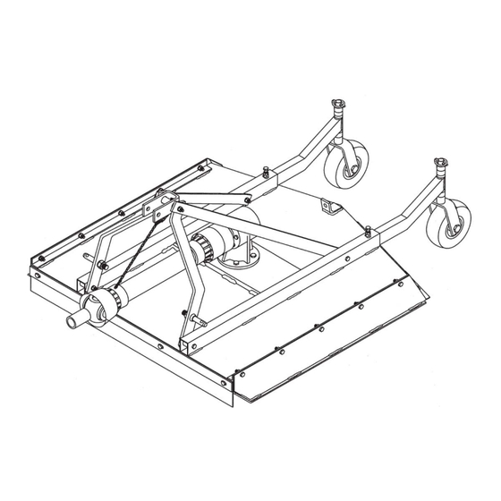
ROTARY MOWER ASSEMBLY INSTRUCTIONS STEP 1 With rotary mower lying flat on the ground, remove the wire holding lift pins and PTO shaft from mower. Remove bolts from the free end of the lift arm braces. Remove bolts attaching lift arms and lift arm braces to the mower. Remove bolt holding swivel link assembly from lift arm brace. - Page 9 Figure A Figure B...
- Page 10 ROTARY MOWER ASSEMBLY INSTRUCTIONS continued... STEP 8 At this time, tighten the four (4) 5/8" x 3-1/2" bolts attaching the lift arms and the lift arm braces to the mower. Also tighten the 5/8" x 6-1/2" bolt that joins them with the swivel link assembly. STEP 9 Lift the rear of the mower high enough for the tail wheels to be out of contact with the ground.
-
Page 11: Before Putting Into Service
BEFORE PUTTING ROTARY MOWER INTO SERVICE (IMPORTANT-INSTRUCTIONS PRIOR TO START UP) SHIPPED WITHOUT OIL IN GEAR BOX AND WITHOUT BEING GREASED. UNIT MUST BE SERVICED BEFORE USING. Fill Gearbox using Multi-Purpose Gear Oil (I.E. S.A.E. 80w/90 or • S.A.E. 85w/140 Multi-purpose gear oil.) For all Grease Fittings use TYPE/grade II tube grease. -
Page 12: Safety Training
SAFETY TRAINING Safety is a primary concern in the design and manufacture of our product. Unfortunately, our efforts to provide safe equipment can be wiped out by a single careless act of an operator or bystander. In addition to the design and configuration of equipment, hazard control and accident prevention are dependent upon the awareness, concern, prudence and proper training of personnel involved in the operation, trans- port, maintenance and storage of this equipment. - Page 13 PREPARTION Never operate the tractor and mower until you have read and completely understand this manual, the Tractor Operator’s Manual, and each of the safety messages found on the safety signs on the tractor and mower. Personal protection equipment including hardhat, safety glasses, safety shoes, and gloves are recommended during assembly, installation, operation, adjustment, maintenance, re- pairing, removal, or moving the implement.
-
Page 14: Operational Safety
OPERATIONAL SAFETY The use of this equipment is subject to certain hazards that cannot be protected against by the mechanical means or product design. All opera- tors of this equipment must read and understand this entire manual, pay- ing particular attention to safety and operating instructions, prior to using. If there is something in this manual you do not understand, ask your su- pervisor, or your dealer, to explain it to you. - Page 15 OPERATIONAL SAFETY continued... Never allow the cutting blade to contact such items. Cut material higher at first, allowing finishing mower to clear hidden objects. Never assume an area is clear. Always Check! Always stop the tractor, disengage PTO, set brake, shut off the tractor engine, remove the ignition key, lower implement to the ground and allow cutter blades to come to a complete stop before dismounting tractor.
-
Page 16: Transportation Safety
OPERATIONAL SAFETY continued... Pass rotary mower diagonally through sharp dips and avoid sharp drops to prevent “hanging up” tractor and rotary mower. Practice will improve your skills in maneuvering on rough terrain. Always cut down slopes; never across the face. When using a unit, a minimum 20% of tractor and equipment weight must be on tractor front wheels. -
Page 17: Attaching To Tractor
ATTACHING TO TRACTOR WARNING Never stand between tractor and rotary mower while backing up tractor to the hitch. STEP 1 Attach to tractor's category 1 three point hitch as described in the Tractor's Operator’s Manual. STEP 2 Determine if the PTO shaft needs to be shortened. NOTE: Due to the many variations in the tractor hitch points and distances be- tween equipment gearbox input shaft and tractor PTO output shafts,... - Page 18 ATTACHING TO TRACTOR continued... STEP 6 Raise rotary mower and remove blocking. Raise and lower rotary mower in order to locate the longest distance between equipment input shaft and the tractor PTO output shaft. With the rotary mower in the longest distance position shut down the tractor and SECURELY BLOCK THE ROTARY MOWER IN POSITION.
-
Page 19: Sizing Pto
SIZING PTO SHAFT STEP 1 Cutting the PTO shaft to length. NOTE: Be sure to cut equal lengths of each PTO shaft section. Clamp end of PTO shaft in a vice and cut off shield where marked. Figure 1-A (Figure 1-A & 1-B) STEP 2 Using cut section of the shield as a guide cut shaft off the same... -
Page 20: Operating Instructions
OPERATING INSTRUCTIONS CUTTING HEIGHT ADJUSTMENT To prevent blades from striking the ground your rotary should be set to the highest position that will give desired grass height. By setting your mower up this way you reduce blade wear and stress on the mower. Mowing at regular intervals will yield far better results than periodic mowing. - Page 21 ROTARY MOWER OPERATION STEP 1 Before each use perform the maintenance described in maintenance section on page 24. STEP2 Read, understand, and follow the information on safety training, preparation, starting and stopping safety, operational safety, transport safety warning sec- tions of this manual (pages 14 thru 18) STEP 3 With tractor running, lower rotary mower to ground so that the deck surface of the mower is parallel to the ground.
-
Page 22: Maintenance
MAINTENANCE Periodically check and maintain proper gear oil level. Every 8 hours, grease wheel forks (4), wheel axles (4), PTO shaft univer- sal joints (2), and PTO telescoping surface. NOTE: Use only a grade Type II tube grease. Before each use check to make sure all safety features are installed and working properly. -
Page 23: Maintenance Safety
MAINTENANCE SAFETY Good maintenance is your responsibility. Poor maintenance is an invitation to trouble. Follow good shop practices. Keep service area clean and dry Be sure electrical outlets and tools are properly grounded Use adequate light for the job at hand. Make sure there is plenty ventilation. -
Page 24: Safety Decal's And Locations
SAFETY SIGN LOCATIONS The types of safety signs and locations on the equipment are shown in the illustration below. Good safety requires that you familiarize yourself with the various safety signs, the type of warning and the area, or particular function related to that area, that requires your SAFETY AWARENESS REMEMBER: IF safety signs have been damaged, removed, become illegible or parts have been replaced without signs, new safety signs must be applied. - Page 28 MODEL NO. DESCRIPTION SN# XXXXXXXXXX...
-
Page 29: Pto Shaft Parts
29" PTO 147029 Ref. Part Name 147029 Roll Pin Kit 500131 Male Tube End Yoke 151045 Implement End Yoke 151040 Female Tube End Yoke 151050 Tractor End Yoke 151035 Inner Tube 14 Series 151090 Outter Tube 14 Series 151091 Cross Kit #4 170015 Quick Disconnect Pin 170110... -
Page 30: Replacement Parts
XB KUTTER... - Page 31 Ref. Part Name Part Number CAT 1. Lift Pins (Pkg. of 2) 500001 Lift Arm 311100 LIft Arm Brace 311099 Swivel Link Kit (inc. bolt) 501027 Right Side Panel Kit (inc.bolts) 501003 Lift Arm Attachment Kit (inc. bolts) 501005 Gear Box 184000 Belt Guard Kit (inc.
-
Page 32: Gearbox Parts
40 HP GEARBOX... - Page 33 Ref. Part Name Gearbox 184000 Snap Ring 106138 Input Seal (NAK35X54X10) 156010 Front Cap 129015 Front Cap Gasket 124130 Snap Ring 131031 Snap Ring 131030 Bearing (Hoover 208) 155005 Input Gear 185007 Input Shaft 186010 Bearing (NSK6207) 155010 Housing 129010 Output Shaft 185005 Spacer...
- Page 34 NOTES:...
-
Page 35: Warranty
1. Limited Warranty. King Kutter, Inc. (“King Kutter”), P.O. Box 1200, Winfield, Alabama 35594, warrants to the original retail purchaser (“Purchaser”) that the product that is the subject of this sale is free from defects in material and workmanship at the time of sale. Under this warranty, King Kutter will repair the defective product free of charge to the Purchaser, with either new or used and reconditioned replacement parts.
Need help?
Do you have a question about the XB and is the answer not in the manual?
Questions and answers