
Summary of Contents for SILTRONIX LA-600
- Page 1 SILTRONIX MODEL LA-600 RF Amplifier OPERATING/SERVICE MANUAL SILTRONIX 330 VIA EL CENTRO OCEANSIDE, CALIFORNIA 92054 Original manual print date unknown Copyright 2007 Donald W. Thomas, K5ZRQ Artwork and Diagrams by Bennie Bolin...
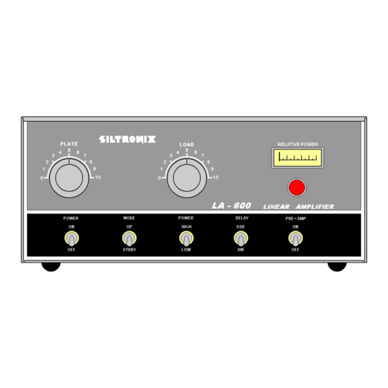
- Page 2 PCB layout were drawn by B. Bolin and were verified against a LA-600. The Siltronix Model LA-600 is designed for operation in the 26 to 30 megacycle range. Due to the high efficiency of the “Single Band” design, it is an excellent amplifier for the Ten Meter Amateur Radio Operator, or for other services outside the United States.
-
Page 3: Specifications
1.1 SPECIFICATIONS: Power Ratings: SSB 800 Watts Nominal PEP Output on High Power AM 500 Watts Nominal Output on High Power AM 300 Watts Nominal Output on Low Power Frequency Coverage: 26.0 to 30.0 MC Tube Complement: Four 8950’s in grounded grid and one 8950 Driver in grounded cathode. RF Drive Requirements: AM Operation - Nominal 3 Watts Single Sideband - Nominal 7 Watts PEP... -
Page 4: Installation
Connect a short length of coaxial cable (RG-58 or RG-8) from the exciter (transceiver or transmitter) to the “INPUT” jack on the rear of the LA-600. A PL-259 connector is required to connect the coax cable to the amplifier. Coax cable should be as short as possible. - Page 5 Allows the relay to remain in “Transmit” mode during short pauses while transmitting. AM Position: Continuously keeps the LA-600 in the transmit mode so long as the exciter is in transmit. 5. PRE-AMP: OFF Position: Exciter receives signal directly from antenna.
- Page 6 (transceiver) to operate directly into the antenna. This also allows any adjustment to be made to the exciter before operating the LA-600. Use this setting for checking drive power. 2. Initial tune-up should be accomplished with the exciter (transceiver) set at the middle range of the frequencies to be operated.
-
Page 7: Initial Tune-Up
6. Key exciter (transceiver) in transmit mode (AM). If single sideband is the only mode available, tune-up of the LA-600 can be accomplished by a sustained whistle into the microphone while holding the push-to-talk button down. In the AM mode, it is only necessary to press the push-to-talk button on the microphone (do not talk into the microphone in this mode). -
Page 8: Circuit Description
5.0 CIRCUIT DESCRIPTION: The LA-600 is a classic TV Sweep Tube Amplifier using five 8950 tubes. One of the tubes is a grid driven driver stage and the other four are the PA tubes in grounded grid final operation. It has a low and high power output setting and features a pre-amplifier which provides approximately 6 db gain on received signals. -
Page 9: Pcb Layout
There are 12 points shown in the drawing by a number inside a circle. These points are connections from the PCB to various points in the LA-600 as indicated by the labeling. - Page 10 7.0 ALIGNMENT: ALIGNMENT – LA-550, LA-600, LA-650 This alignment procedure applies to the LA-550, LA-600, and LA-650 amplifiers. 1. Driver Neutralization A. Connect RF Voltmeter to the cathodes of the four PA tubes. If a RF Voltmeter is not available, an Oscilloscope with a bandwidth over 30 Mhz can be used with a 10X Probe.
-
Page 11: Parts List
8.0 PARTS LIST: Capacitors Ref# Description NOTES: .01uF Ceramic Disc AC Input bypass .01uF Ceramic Disc AC Input bypass .0022uF Ceramic Disc HV Section .0022uF Ceramic Disc HV Section .0022uF Ceramic Disc HV Section .0022uF Ceramic Disc HV Section 225uF 300VDC Electrolytic HV Section, CG2250T300B1 225uF 300VDC Electrolytic HV Section, CG2250T300B1... - Page 12 Capacitors Ref# Description NOTES: 105pF, Air Variable, PA TUNE PA Section 710pF, Air Variable, PA LOAD PA Section, Marked 074-062ASP7341 39 pF Ceramic Disc On PCB 33 pF Ceramic Disc On PCB .01uF Ceramic Disc On PCB 10 pF Ceramic Disc On PCB .01uF Ceramic Disc On PCB...
- Page 13 Resistors Ref# Description NOTES: 2.2K 2W Driver Section 68K 1/2W On PCB 1K 1/2W On PCB 10K 1/2W On PCB 220 1/2W On PCB 470 1/4W On PCB 22K 1/4W On PCB 220 1/2W On PCB 6.8K 1/4W On PCB 3.3K 1/2W On PCB 22K 1/4W...
- Page 14 Tubes Ref# Description NOTES: 8950 Driver Section 8950 PA Section 8950 PA Section 8950 PA Section 8950 PA Section Switches, Fuses, Relays, Lamp, Misc Ref# Description NOTES: 15 Amp SPST AC POWER Switch SPDT MODE Switch DPST RF POWER Switch SPDT DELAY Switch DPST...
-
Page 15: Power Transformer
9.0 POWER TRANSFORMER: USING TRANSFORMER 271-025 (10 LEADS) WITH LA-550, LA-600, and LA-650 The original power transformer used in the LA-550, 600 and 650 series linear amplifiers was the 9 or 8 lead version of the 271-025. If the linear uses 6LF6 tubes it has the 9 lead version, because of the requirement to provide 6 volts to the filament of the driver tube. - Page 16 Disassembly: Carefully drill off the braded end of the two rivets holding the switch together using a small drill bit. Then push the rivets out of the switch while holding the switch front and back. Once the rivets are removed, the internal spring will be pushing the switch apart. Lift the top cover off while watching where all the pieces are located.
-
Page 17: Warranty Policy
All returns for repairs must be freight prepaid. This equipment is manufactured for use on such frequencies as authorized by the FCC. Siltronix does not accept any responsibility for un-authorized use of such equipment.
Need help?
Do you have a question about the LA-600 and is the answer not in the manual?
Questions and answers