Table of Contents
Advertisement
Technical And User Manual
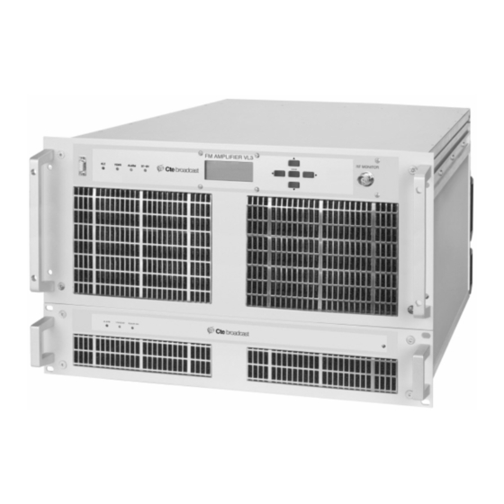
VL3 2500W FM AMPLIFIER
VL3 FM Radio Amplifier
User Manual
Issued: January 2008 -Version 3
CTE Digital Broadcast
Via Gadames 93 - 20151
Milano (Italy)
This document may be duplicated or otherwise used or its contents made known to third parties only
with permission of the originator or other authorized people.
Infringements constitute an offence and are subject to claim for damages.
All rights reserved for patenting or utility model registration.
Advertisement
Table of Contents

Summary of Contents for CTE VL3 FM
-
Page 1: User Manual
Technical And User Manual VL3 2500W FM AMPLIFIER VL3 FM Radio Amplifier User Manual Issued: January 2008 -Version 3 CTE Digital Broadcast Via Gadames 93 - 20151 Milano (Italy) This document may be duplicated or otherwise used or its contents made known to third parties only with permission of the originator or other authorized people. -
Page 2: Technical Characteristics
VL3 2500W FM AMPLIFIER VL3 FM Radio 2500W amp. 88 - 108 MHz The VL3 is a solid state FM amplifier with 2500W output power using MOSFET devices of last generation. The RF amplification stage is separated from the Power Supply Unit in order... -
Page 3: Table Of Contents
Mains line power cord connection .................. 27 3.1.4 DB15 Parallel connection PIN Specification..............28 3.1.5 Turning the system ON ....................28 3.1.6 Cares and maintenance....................29 3.1.7 Menu Display........................29 Mechanical Dimensions........................34 Technical Specifications ......................... 35 File schematics diagram........................36 CTE Digital Broadcast... -
Page 4: General Safety And Warning Recommendations
NOTE: This section is not intended to contain a complete statement of all safety precautions which should be observed by personnel in using this electronic equipment or others. CTE International shall not be responsible for injury or damage resulted from improper procedures or from using it by improperly trained or inexperienced personnel. -
Page 5: General Safety Recommendations
• When inserting or removing printed circuit boards (PCBs), cable connectors, or fuses, always turn off power to the affected portion of the equipment. After power is removed, allow sufficient time for the power supplies to bleed down before reinserting PCBs. CTE Digital Broadcast... -
Page 6: First Aid In Case Of Electrical Shock
Position the person flat on their back. Kneel by their side and place one hand on the forehead and the other under the chin. Tilt the head back and lift the chin until teeth almost touch. Look and listen for breathing. CTE Digital Broadcast... - Page 7 Position your hands in the center of the chest between the nipples. Place one hand on top of the other. Step 6 Push down firmly two inches. Push on chest 15 times. CONTINUE WITH TWO BREATHS AND 15 PUMPS UNTIL HELP ARRIVES. CTE Digital Broadcast...
-
Page 8: Treatment For Burns
• Never permit burned surfaces to be in contact with each other, such as: areas between the fingers or toes, the ears and the side of the head, the undersurface of the arm and the chest wall, the folds of the groin, and similar places.. • Transport to a medical facility CTE Digital Broadcast... -
Page 9: Warning Instruction
OFF positions and the mains line cable is connected. If it is really necessary and after authorization of CTE very qualified technical staff only can work with on live parts. In this special case special safety precautions must be taken. CTE declines any responsibility if any safety rule is not respected. -
Page 10: Vl3 Warning
The air filters must be periodically cleaned and replaced if damaged. Once the installation of the system including cables and antennas is completed, it must be in compliance with the EMF clauses advised in the 1999/519/EC normative. CTE Digital Broadcast... - Page 11 OXIDE broken, crashed or heated. OBSERVE SAFETY This oxide passes through the INSTRUCTIONS ! common systems of filtering, including the respiratory apparatus. The prolonged inhalation at high degrees causes poisoning with respiratory apparatus paralysis, until death. CTE Digital Broadcast...
-
Page 12: Vl3 General Description
2 The AUX cable, used to connect the ± 20Vdc to the control signal necessary for the management of the equipment and provided by the microprocessor Board placed on the RF UNIT. COMPOSITION VL3 ( rear view) CTE Digital Broadcast... -
Page 13: Vl3 Block Diagram
Technical And User Manual VL3 2500W FM AMPLIFIER 2.2 VL3 BLOCK DIAGRAM Vcc1 1250W RF out 2500W Vcc2 Directional Coupler RF Input Detect Unb. 50W max 1250W RF UNIT 2.5KW Vcc1 PS1 1800W Vcc2 PS2 1800W PS3 1800W Scheda Shunt 3 x PS 1800VA... -
Page 14: Front Panel Description
Technical And User Manual VL3 2500W FM AMPLIFIER Front Panel Description RF PROBE Stand-By Alarm ALC VSWR RS232 19" Amplifier Front Panel Amplifier Rear Panel... - Page 15 Output connector, Flange 7/8. Input for the Mains Line power cord External Interface AUX PS: Used For Power Supply Connection DB15: Used for remote analogue control LAN: RJ45 for TCP/IP ans SNMP connection RS485: Internal BUS CONNECTION CTE Digital Broadcast...
-
Page 16: Rf Unit Description
2500W unit includes a built-in dummy load that in case of breakdown of one module assures continuity of on-air operation. The unbalanced dummy load can stand up to 800W continuous. INPUT 1250W OUT 2500W Unbalanced Load -3dB 90° 2500W Combiner CTE Digital Broadcast... - Page 17 Menu, but for the protections of the ALC and VSWR figures as well. The RF output is terminated with 7/8” EIA Flange. Nominal Power 350W Picture of the RF MODULE, 2,5KW. Detail of the RF module, 1,3KW CTE Digital Broadcast...
-
Page 18: 1300W Rf Module Description
The toroidal ferrite cores of the output transformer may be damaged by strong magnetic fields created by electrical currents. This situation may arise in the event of failure of a FET device. CTE Digital Broadcast... -
Page 19: Low Pass Filter And Directional Coupler
On the same line a signal for an “RF Proble” is taken at 40bD equalized in band . CTE Digital Broadcast... -
Page 20: Ext Interface
I.C. UDS14C232 via the RS232 port, and by the I.C. DS75175 via the RS485 port. The I.C.’s LM336 and LM358 are the interfaces between the temperature sensor placed on the power amplifier and the input of the microprocessor. CTE Digital Broadcast... -
Page 21: Fuse Board
14Kgs. Only. The PSU is composed by three power supply boards able to operate with a nominal current of 35A at 50Vdc. The three local power supply are connected in parallel and are controlled by the connection named “Current Share”, which always guarantees a perfect balance of the CTE Digital Broadcast... -
Page 22: Power Supply Unit
-2.2 dB instead of -6dB of the standard configuration. • Equal and balanced working condition for all the PS connected to the parallel CTE Digital Broadcast... -
Page 23: Power Supply Board Description
SMPS operation. SMPS4834 also provides auxiliary voltages to supply external electronic circuits and fan . A detailed block diagram of the circuit is shown in following paragraph. Electrical connections and pins out are described further . CTE Digital Broadcast... -
Page 24: Power Supply Protections
. The fans will keep on cooling the SMPS. Whenever the temperature gets under the established threshold, the SMPS will turn on and will leave the stand-by condition , bringing to normal operation the power supply. Block diagram of the single Power Supply 1800W@ 48Vdc CTE Digital Broadcast... -
Page 25: Over Current Protection
This condition occurs when the output current exceeds the maximum value. When the over current protection is activated, the output voltage drops under 48V, thus keeping the output current figure nearly constant. The SMPS automatically recovers when the over-current condition is removed. Power Supply Unit: internal view CTE Digital Broadcast... -
Page 26: Putting In Operation Instructions
• With 400V mains voltage: use 1,5 mm (minimum section). Do not mount the three jumpers on the terminal board. Prior to ignition, make sure that the neutral is duly connected to the equipment and that the ground connection is mounted. CTE Digital Broadcast... -
Page 27: Mains Line Power Cord Connection
VL3 2500W FM AMPLIFIER 3.1.3 Mains line power cord connection THREE-PHASE Connection. SINGLE-PHASE Connection. CTE Digital Broadcast... -
Page 28: Db15 Parallel Connection Pin Specification
’’Normal’’ (normal working condition). The back illumination of the LCD Display should stay on for about 30 minutes after the last button has been pressed. Check the figures of the forward and of the reflected RF power . CTE Digital Broadcast... -
Page 29: Cares And Maintenance
10 Power Supply Alarm ( active with one o more of the following: Overload; Over-current; Faulty) 11 Stand-by Remote (activated by RS232/RS485 o LAN) 12 Interlock Status 13 Stand-by DB15(activated by parallel interface DB15) < Normal >=Normal Condition <Alarm Stand By>=Stand By condition by ext command CTE Digital Broadcast... - Page 30 Front panel display key Go page down, or decrease value Go page up, or increase value Go left position Go right position Confirm of changing data ENTER [ xxx ] The Square Parenthesis indicate the active choice CTE Digital Broadcast...
- Page 31 IPA1 and IPA2 ) 3. SUPPLY ( shows the PS voltage: Vpsu ) 4. TEMPERATURE ( shows the temperature of the two RF heat sink and the internal unbalanced load: TPA1 and TPA2 , TLOAD. 5. DATA/ HOUR CTE Digital Broadcast...
- Page 32 9. HISTORY CLEAR ( cancel the alarm history ) 10. STAND BY ( active the Stand-By Command) 11. RS 485 ADDRESS 12. FW UPDATE ( softwawe upgrade) Move to change from the above possibility and press to go in the Sub Menu. CTE Digital Broadcast...
- Page 33 MENU ALARM HISTORY ALARM The indication MOn shows the quantity of the alarms. In figure are 7. The History can be deleted pressing “HISTORY CLEAR” available on the MO 7 PARAMETERS MENU. CTE Digital Broadcast...
-
Page 34: Mechanical Dimensions
VL3 2500W FM AMPLIFIER 4 Mechanical Dimensions Power Supply Unit RF Amplifier Unit CTE Digital Broadcast... -
Page 35: Technical Specifications
Power Supply Unit Type switching Mono phase PFC active type PF 0,98 230 Vac ± 15% Single Phase Input Voltage 400 Vac ± 15% Three-Phase Input Voltage R.M.S. Input current (50V) 8,5A, 230Vac Efficiency Current 34A (48V) CTE Digital Broadcast... -
Page 36: File Schematics Diagram
Layout components K3142 2Way input divider K3188-EL Electrical schematics K3142 2Way input divider K3188-PL Part List K3142 2Way input divider K3188-LY Layout components K3188 2Way Output coupler K3188-EL Electrical schematics K3188 2Way Output coupler K3188-PL Part List CTE Digital Broadcast... - Page 37 K3191 Low Pass Filter K3191-LY Layout components K3192 Controller K3192-EL Electrical schematics K3192 Controller K3192-PL Part List K3192 Controller K3192-LY Layout components K3186 PSU-Interface K3186-EL Electrical schematics K3186 PSU-Interface K3186-PL Part List K3186 PSU-Interface K3186-LY Layout components CTE Digital Broadcast...
Need help?
Do you have a question about the VL3 FM and is the answer not in the manual?
Questions and answers
Good Day sir am using vl3 is showing low voltage pls what is the problem
Low voltage issues with the CTE VL3 FM could be caused by several factors based on the context:
1. Incorrect adjustment of trimmers: The trimmers RV8 and RV9 adjust the DC voltage display. If misadjusted, they could indicate or cause incorrect voltage levels.
2. Control voltage failure: The -15V auxiliary control voltage is critical. If it fails, the microprocessor will turn off the amplifier, potentially causing low or no voltage output.
3. Fuse issues: Blown quick-break fuses on the fuse board can interrupt power to specific RF blocks, lowering the total output voltage.
4. Short circuits in RF blocks: These could trigger fuses and reduce voltage to only the healthy stages.
5. Faulty constant current generator: If transistor Q3 or associated components fail, it may not maintain the required 10V bias voltage, affecting output.
6. Directional coupler or low pass filter problems: Faults here could affect feedback to the microprocessor, leading to power reduction.
7. Shunt or current sensing issues: Faulty shunts might misreport current, leading the system to reduce voltage output for protection.
Each of these should be checked by authorized personnel during maintenance or troubleshooting.
This answer is automatically generated
How to change the network parameters. This option isn't available in the setting menu.