ACU-RITE 200S READOUTS Reference Manual
Keypad
Hide thumbs
Also See for 200S READOUTS:
- Step-by-step instructions (16 pages) ,
- Step-by-step instructions (16 pages) ,
- Reference manual (43 pages)
Table of Contents
Advertisement
Quick Links
Advertisement
Table of Contents

Related Manuals for ACU-RITE 200S READOUTS


Summary of Contents for ACU-RITE 200S READOUTS
- Page 1 200S R EADOUTS REFERENCE MANUAL...
-
Page 3: 200S Soft Keys
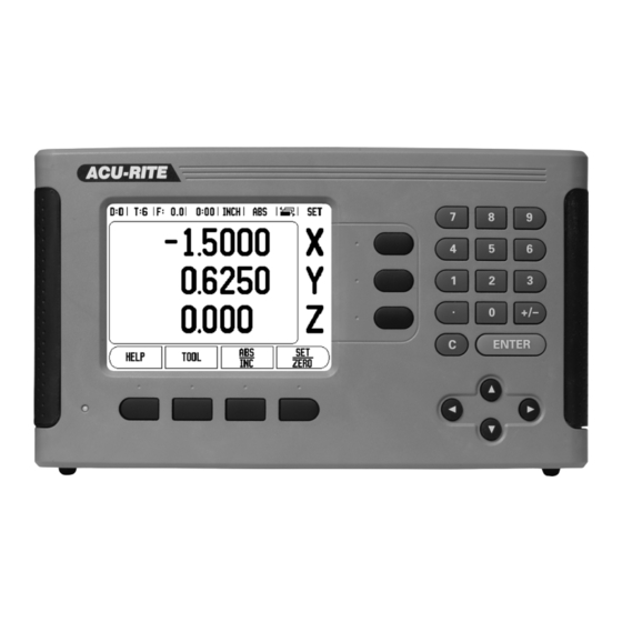
200S Key Layout Display Area Soft keys Power Indicator light Arrow Keys: Use the UP/DOWN keys to adjust the screen contrast. Axis Keys Numeric Keypad ENTER key CLEAR key 200S Soft keys There are multiple pages of soft key functions to select from the operating modes. - Page 4 Soft Key function (Page 2) Soft key Press to select the Circle Pattern, Linear Pattern, Incline Mill, or Arc Mill table. This function is for Milling applications only (page 28). This soft key toggles between radius and diameter displays. This function is for Turning applications only (page 41).
-
Page 5: Readout Parameter Access Code
Readout Parameter Access Code An access code must be entered before machine-related installation parameters can be set or changed. This prevents inadvertent adjustments to the installation setup parameters. IMPORTANT! The access code is 8891. Access to Machine Parameter Operations Refer to the Setup section also. Begin by pressing the SETUP soft key. -
Page 7: Introduction
Introduction Software Version The software version is shown on the initial power up screen. This User's Manual covers the functions of the 200S for both milling, and turning applications. Operational information is arranged in three sections: General Operations, Mill Specific Operations, and Turn Specific Operations. -
Page 9: Hassle-Free Warranty
In addition, authorized ACU-RITE service representatives will provide service labor (field service) for a period of one (1) year at no charge. Notice of the claimed defect must be received by ACU-RITE within the warranty period. This warranty applies only to products and accessories installed and operated in accordance with this reference manual. - Page 10 viii...
-
Page 11: Table Of Contents
Table of Contents 200S Key Layout ......................i 200S Soft keys......................i Readout Parameter Access Code Access to Machine Parameter Operations .............. iii Introduction Software Version ......................v 200S ...................v DRO axis availability Symbols within Notes....................v 200S Fonts........................v Hassle-Free Warranty ..................vii 3-Year Hassle-Free Warranty I - 1 Fundamentals of Positioning Datums ........................ - Page 12 Measured Value Output..................13 Near Zero Warning.................... 13 Status Bar Settings ................... 14 Job Clock ......................14 Remote Switch ....................14 Console Adjustment ..................15 Language ......................15 Import/Export ....................15 Viewing the main operating screen: ..............16 Set/Zero Soft Key....................16 Distance to Go “INC”...
- Page 13 I - 4 Turning Specific Operations Tool Display Icon....................36 Tool Table......................36 Setting Tool Offsets..................36 Datum Setting....................38 Taper Calculator ....................40 Presets......................41 Radius/Diameter ....................41 Vectoring......................42 Z Coupling ......................42 Enabling / Disabling Z0, and Z Coupling ............43 II - 1 Installation Setup Installation Setup Parameters ................
- Page 14 II - 4 I/O Connections Pin layout for Electronic Edge Finder ..............56 Wiring the Serial communication cable ............57 II - 5 Remote Switch Data Output Data output using external signals..............58 Data output using Edge Finder ................. 60 II - 6 Dimensions DRO Dimensions ....................
- Page 15 Operating Instructions...
-
Page 16: I - 1 Fundamentals Of Positioning
I - 1 Fundamentals of Positioning Datums The workpiece drawing identifies a certain point on the workpiece (example: “a corner”) as the absolute datum, and perhaps one, or more other points as relative datums. The datum setting procedure establishes these points as the origin of the absolute, or relative coordinate systems. -
Page 17: Absolute Workpiece Positions
Absolute Workpiece Positions Each position on the workpiece is uniquely identified by its absolute coordinates. Example: Absolute coordinates of position 1: X = 20 mm Y = 10 mm Z = 15 mm If you are drilling, or milling a workpiece according to a workpiece drawing with absolute coordinates, the tool is moving to the value of the coordinates. -
Page 18: Zero Angle Reference Axis
Zero Angle Reference Axis The Zero Angle Reference Axis is the 0.0° position. It is defined as one of the two axes in the plane of rotation. The following table defines the Zero Angle where the position of the angle is zero for the three possible planes of rotation. -
Page 19: Encoder Reference Marks
Encoder Reference Marks Encoders normally contain one or more reference marks which the 200S Reference Mark Evaluation feature uses to re-establish datum positions after a power interruption. There are two main options available for reference marks; fixed and distance-coded. Distance-coded reference marks: Encoders that have marks separated by a specific encryption pattern allows the 200S to use any two pair of marks along the length of the encoder to re-establish the prior datums. -
Page 20: I - 2 General Operations For 200S
11 Soft key Labels 12 Display Area 13 Near Zero Warning (In Distance-To-Go mode only) ACU-RITE’s 200S readout provides application-specific features that allows you to obtain the most productivity from your manual machine tools. Status Bar - This displays the current datum, tool, feed rate, job clock time, unit of measure, operating mode status, page indicator, and set/zero. -
Page 21: General Navigation
General Navigation Use key pad to enter numeric values within each field. The ENTER key will confirm the entry within a field, and return to the previous screen. Press the C key to clear entries, and error messages, or return back to the previous screen. -
Page 22: Reference Mark
Reference Mark The 200S reference mark feature automatically re-establishes the relationship between axis slide positions, and display values last defined by the datum setting following a power cycle. First time power up require these values to be defined along with all initial DRO setting. Press the NO REF softkey, and use the RIGHT, or LEFT arrow keys to enter SETUP. -
Page 23: Working Without Reference Mark
Working without reference mark The 200S can also be used without crossing over the reference marks. Following a power cycle, do not move any axes. Press the NO REF soft key to exit the reference mark routine, and continue. The 200S can still cross over reference marks at a later time. -
Page 24: Operating Modes
Operating Modes The 200S has two operating modes: Distance-To-Go (INCREMENTAL), and Actual Value (ABSOLUTE). The Actual Value mode always displays the current actual position of the tool, relative to the active datum. In this mode, all moves are done by traveling until the display matches the nominal position that is required. -
Page 25: Setup
Setup 200S offers two categories for setting up operating parameters. These categories are: JOB SETUP ,and INSTALLATION SETUP. The JOB SETUP parameters are used to accommodate specific machining requirements for each job. INSTALLATION SETUP is used to establish encoder, and display parameters. In this section, the JOB SETUP parameters are provided. -
Page 26: Scale Factor
Scale Factor The scale factor may be used to scale the part up or down. A scale factor of 1.0 creates a part with the exact size as dimensioned on the print. A scale factor >1 “grows” the part, and <1 “shrinks” the part. The following probing soft key functions are available: The numeric keys are used to enter a number greater than zero. -
Page 27: Diameter Axes
Diameter Axes Select Diameter Axes to bring up the diameter screen shown here to set which axes can be displayed in either radius or diameter values. ON indicates that the axis position will be displayed as a diameter value. When OFF, the Radius/Diameter feature does not apply. For turning applications see "Radius/Diameter Soft Key"... -
Page 28: Status Bar Settings
Status Bar Settings The Status Bar is the segmented bar at the top of the screen which displays current datum, tool, feed rate, job clock and page indicator. Press the ON/OFF soft key for each setting you want to see displayed. -
Page 29: Console Adjustment
While in the Zero Field, press the appropriate axis keys to enable or disable zeroing of the axis display positions when the switch is closed. While in the Next Hole Field, press the ON/OFF soft key to ON to move to the next hole within a pattern. -
Page 30: Viewing The Main Operating Screen
Viewing the main operating screen: Set/Zero Soft Key The SET/ZERO soft key [1], is a toggle key that determines the effect of pressing an axis key [2]. Pressing the SET/ZERO soft key switches the functionality between “SET”, and “ZERO” [3]. The current setting is indicated in the Status Bar [3]. -
Page 31: Distance To Go "Inc
Distance to Go “INC” When in the “SET”, and Distance-To-Go “INC” mode, pressing an axis key [2] opens the PRESET form. The preset Distance-To-Go value shown is the previous preset value entered. New preset values can now be entered. The values can include incremental by pressing the I soft key, and tool offset by pressing the R +/- soft key. -
Page 32: I - 3 Milling Specific Operations
I - 3 Milling Specific Operations This section discusses operations, and soft key functions specific to milling applications only. Soft Key Functions Tool Soft Key The TOOL soft key opens the tool table, and provides access to the Tool form for entering a tool’s parameters. The 200S can store up to 16 tools within the tool table. -
Page 33: Tool Compensation
Tool Compensation This allows workpiece dimensions directly from the drawing to be entered. R represents the tool radius, and examples of the R values are shown here. The displayed distance to go is then automatically lengthened R+, or shortened R- by the value of the tool radius. For more information see "Presets"... -
Page 34: Calling The Tool From The Tool Table
Calling the Tool from the Tool Table To call a tool, press the TOOL soft key. Use the UP, or DOWN arrow keys to cursor through the selection of tools (1-16). Select the tool required by highlighting that tool. ... -
Page 35: Probing With A Tool
Probing with a Tool If using a tool, or non-electrical edge finder to set datum points, the 200S probing functions can still be used. Datum points can be set by touching the edges of a workpiece, one after the other with a tool, and then manually entering the tool’s position as datum points. -
Page 36: Example: Probe Workpiece Edge And Set Edge As Datum
Example: Probe workpiece edge and set edge as datum Preparation: Set the active tool to the tool that will be used to set the datum. An end mill is shown in this example, along with the Set Datum screen. Datum axis: X =0 Tool diameter D = 0.25”... -
Page 37: Presets
Presets The Preset function is used to indicate the nominal (target) position for the next move. Once the new nominal position information is entered, the display will switch to Distance-To-Go mode. It will show the distance between the current position and the nominal position. Now the table only needs to move until the display is zero, and will be at the required nominal position. - Page 38 Preparation: Select the tool with the appropriate tool data. Pre-position the tool to an appropriate location (such as X = Y = -1”). Move the tool to milling depth. Pressthe PRESET soft key. Press the Y axis key -ALTERNATIVE METHOD - ...
-
Page 39: Incremental Distance Preset
Incremental Distance Preset Example: Drilling by traversing to display value zero with incremental positioning. Enter the coordinates in incremental dimensions. These are indicated in the following (and on the screen) with a preceding I (Incremental). The datum is the workpiece zero. Hole 1 at: X = 1”... -
Page 40: 1/2 Soft Key
To preset the location for Hole 2: Press the PRESET soft key. Press the X axis key. Enter nominal position value for hole 2: X = 1.5”, mark your input as an incremental dimension, press the I soft key. ... -
Page 41: Circle, And Linear Patterns
Circle, and Linear Patterns This section describes the hole pattern functions for Circle and Linear patterns. Press the CIRCLE, or LINEAR PATTERN soft keys to access the Pattern function, then enter the required data. The 200S calculates the positions of all the holes, and displays the pattern graphically on the screen. -
Page 42: Circle, And Linear Pattern Form
Circle, and Linear Pattern Form The Circle, or Linear Pattern form is used to define one circle hole pattern (Full, or Segment), and one linear hole pattern (Array, or Frame). Access the Pattern Form from the DRO soft key menu by first pressing the LEFT/RIGHT arrows until the FEATURES soft key is shown. -
Page 43: Circle, Or Linear Pattern Execution
Linear Pattern Information Required Type: type of pattern, ARRAY or FRAME. First Hole: location of the first hole of the pattern. Holes per Row: number of holes in each row of a pattern. Angle: the angle, or rotation of the pattern. Depth: the target depth for drilling in the tool axis. -
Page 44: Incline, And Arc Milling
Incline, and Arc Milling This section describes the incline, and arc milling features. They provide ways to machine a flat diagonal surface (incline milling), or a rounded surface (arc milling) using a manual machine. This section describes the Incline, and Arc Mill entry form, and capabilities. -
Page 45: Incline, And Arc Milling
Incline, and Arc Milling The Incline, or Arc Mill entry form is used to define one Incline, and Arc pattern. Access the Mill entry form from the DRO soft key menu by first pressing the LEFT/RIGHT arrows until the FEATURES soft key is shown. -
Page 46: Incline, And Arc Milling Form Entry
Incline, and Arc Milling form entry The following soft keys are available while in the entry form. Function Soft key Press to select a plane ([XY], [YZ], or [XZ] Press to execute the milling operation Press to use the current absolute position Incline Milling The Incline Milling form is used to specify the flat surface to be milled. -
Page 47: Arc Milling
Arc Milling The Arc Milling form is used to specify the curved surface to be milled. The data is entered through this form, and will allow this feature to be defined. The following listed fields require data input. Plane Selection: Select the plane by pressing the PLANE soft key. The current selection is shown on the soft key, and in the plane field. -
Page 48: Incline, And Arc Mill Execution
Incline, and Arc Mill Execution To execute a milling operation, select the feature using the corresponding soft key to open the entry form. Press the RUN soft key. The screen switches to the incremental DRO view, showing the incremental distance from the start point. - Page 49 To follow the contour, move the two axes in small steps, keeping the X, and Y positions as close to zerro (0.0) as possible. When no step size is specified, the incremental display always shows the distance from the closest point on the arc. ...
-
Page 50: I - 4 Turning Specific Operations
I - 4 Turning Specific Operations This section discusses operations specific to turning applications only. Tool Display Icon The Ø icon is used to indicate that the displayed value is a diameter value. No icon visible indicates that the display is a radius value. Tool Table The 200S can store the dimensional offsets for up to 16 tools. - Page 51 Press the ENTER key. Select the axis (X) key. Enter the position of the tool tip, for example, X= Ø .100”. Remember to ensure the 200S is in diameter display mode (Ø) if the input is a diameter value. ...
-
Page 52: Datum Setting
Press the LOCK AXIS soft key while the tool is still cutting. Retract from the current position. Turn the spindle off, and measure the workpiece diameter. Enter the measured diameter, or radius, and press ENTER. Remember to ensure the 200S is in diameter display mode Ø if you input a diameter value. - Page 53 Press the DOWN arrow key to advance to the Z axis. Touch the workpiece surface at point 2. Enter the position of the tool tip (Z= 0) for the Z coordinate of the datum. Press ENTER. Setting Datums using LOCK AXIS Function The LOCK AXIS function is useful for setting a datum when a tool is under load and the diameter of the workpiece is not known.
-
Page 54: Taper Calculator
Taper Calculator Soft Key Use the taper calculator to calculate taper angle. Refer to screen examples on the right. You can calculate tapers either by entering dimensions from a print, or by touching a tapered workpiece with a tool or indicator. Entry values: For the taper ratio, calculation requires: Length of the taper... -
Page 55: Presets
Presets The functionality has been explained previously in this manual (see "Presets" on page 23). The explanation, and examples on those pages are based on a mill application. The basics of those explanations are the same for turning applications with two exceptions; Tool Diameter Offsets (R+/-), and Radius vs. -
Page 56: Vectoring
Vectoring Vectoring breaks down the movement of the compound axis into the crossfeed or longitudinal axes . If you are turning threads, for example, vectoring lets you see the diameter of the thread in the X-axis display, even though you are moving the cutting tool with the compound axis handwheel. -
Page 57: Enabling / Disabling Z0, And Z Coupling
Enabling Z0, and Z Coupling To couple the Z , and Z axes and have the result displayed on the Z display, press and hold the Z key approximately 2 seconds. The sum of the Z positions will be displayed on the Z display and the Z display will be blanked. - Page 59 Technical Information...
-
Page 60: Ii - 1 Installation Setup
II - 1 Installation Setup Installation Setup Parameters To locate the Installation Setup screen from the normal operating display: Press the RIGHT, or LEFT arrow key until the SETUP soft key is displayed Press the SETUP soft key. The Job Setup screen is now displayed, and the INSTALL. - Page 61 Select the encoder type by pressing the LINEAR/ROTARY soft key. Arrow down to the RESOLUTION field. Press COARSER, or FINER soft keys when using linear encoders to select the encoder’s resolution in µm (10, 5, 2, 1, 0.5). The exact resolution can also be typed in using the numeric key pad.
-
Page 62: Display Configuration
Display Configuration The Display Configuration form is where which axes can be selected for display, and in what order. The following additional setups are also available. Scroll to the desired display, and press ENTER. Press the ON/OFF soft key to turn the display on, or off. Press the LEFT, or RIGHT arrow key to select the axis label. -
Page 63: Linear Error Compensation
Linear Error Compensation Linear error compensation can be applied, if the results of the comparison with a reference standard show a linear deviation over the whole measuring length. In this case the error can be compensated by the calculation of a single correction factor. To calculate the linear error compensation use this formula: Correction factor LEC = (S –... -
Page 64: Starting A Non-Linear Error Compensation Table
Starting a Non-Linear Error Compensation Table Select Non-linear by pressing the TYPE soft key. To start a new error compensation table, first press the EDIT TABLE soft key. All correction points (up to 200) are equally spaced from the start point. -
Page 65: Exporting The Current Compensation Table
Viewing the Compesation Table Press the EDIT TABLE soft key. To switch between the table and graph views, press the VIEW soft key. Press the UP, or DOWN arrow keys or the numeric keys to move the cursor within the table. The error compensation table data may be saved to or loaded from a PC via the Serial port. -
Page 66: Serial Port
Serial Port A printer or computer may be connected to the serial port. Job, and Installation Setup parameters may be sent to a printer or computer. Remote commands, remote key codes, and Job, and Installation Setup parameters may be received from a computer. ... -
Page 67: Diagnostics
The Position Recall feature, when it is “ON”, will store the last position of each axis when power was turned off, and then redisplay that position once power is turned back on. Note that any movement that occurs while power is off will be lost. -
Page 68: Rs-232C Serial Communications
II - 2 RS-232C Serial Communications Serial port The RS-232-C/V.24 serial port is located on the rear panel. The following devices can be connected to this port: Printer with serial data interface. Personal computer with serial data interface. For operations that support data transfer, an IMPORT/EXPORT soft key is available. -
Page 69: Installation And Electrical Connections
II - 3 Installation and Electrical Connections Installation The DRO is mounted to a tilt/swivel feature: See "DRO Dimensions" on page 63. Electrical requirements Voltage 100 - 240 Vac Power 30 VA max. Frequency 50/60 Hz (+/- 3Hz) Fuse 630 mA/250 Vac, 5 mm x 20 mm, Slo-Blo (line and neutral fused) Environmental Operating temperature... -
Page 70: Ii - 4 I/O Connections
II - 4 I/O Connections Encoders are plugged into connectors marked Inputs 1, 2, & 3. Pin layout for Electronic Edge Finder Assignment 0V (Inner shield) Stand By 15 Pin receptacle connector for Edge Finder. Switch Signal Grounding Edge Finder / Remote Switch Housing External Shield... -
Page 71: Wiring The Serial Communication Cable
Wiring the Serial communication cable The wiring of the serial communication cable depends on the device being connected (see technical documentation for external device) Pin layout of RS-232-C / V.24 data interface. Pin assignment Assignment Function No assignment - Transmitted Data - Received data - Request to send - Clear to send... -
Page 72: Ii - 5 Remote Switch Data Output
II - 5 Remote Switch Data Output The remote switch (pendant or footswitch), or Ctrl B (sent over serial interface), will transmit the currently displayed values in either Actual Value or Distance-To-Go mode, whichever is currently visible. Data output using external signals Example 1: Linear axis with radius display X = + 41.29 mm <CR>... - Page 73 Example 2: Rotary axis with degrees decimal display C = + 1260.0000° 1 2 6 0 0 0 0 0 W <CR> <LF> Coordinate axis Equal sign +/– sign 4 to 8 places before the decimal point Decimal point 0 to 4 places after the decimal point Blank space W for angle (in distance-to-go display: w Carriage return...
-
Page 74: Data Output Using Edge Finder
Colon 0 to 2 places seconds Blank space W for angle (in distance-to-go display: w Carriage return Blank line (Line Feed) Data output using Edge Finder In the next three examples, measured value output is started with a switching signal from the edge finder. Printing capability can be turned on, or off in the Job Setup parameter Measured Value Output. - Page 75 Example 5: Probing function Centerline Coordinate of centerline on X axis CLX = + 3476.9963 mm (Center Line X axis) Distance between the probed edges DST = 2853.0012 mm (Distance) 3 4 7 6 9 9 6 3 <CR> <LF> 2 8 5 3 0 0 1 2 <CR>...
- Page 76 Example 6: Probing function Circle Center First center point coordinate, e.g. CCX = –1616.3429 mm. Second center point coordinate, e.g. CCY = +4362.9876 mm, (Circle Center X axis, Circle Center Y axis; coordinates depend on working plane). Circle diameter DIA = 1250.0500 mm 1 6 1 6 3 4 2 9 <CR>...
-
Page 77: Ii - 6 Dimensions
II - 6 Dimensions DRO Dimensions Dimensions in inches/mm Top view with Dimensions Back view Front view with Dimensions Bottom view with Dimensions 200S... - Page 79 absolute coordinates 3 General Navigation 7 Absolute Distance Preset 23 General Operations for 200S 6 Absolute Workpiece Positions 3 Grounding (Earth) 55 Actual Position, Nominal Position, and Distance- To-Go 2 Import/Export (setting) 15 Actual Value/Distance-To-Go soft key 10 Incline, and Arc Milling 30 Arc Milling 33 incremental coordinates 3 Axis Labels 6...
- Page 80 Scale factor 12 Screen Layout 6 Set Zero soft key 16 Setting Tool Offsets 36 Setup 11 Setup soft key 11 Soft key Labels 6 Status Bar 6 Taper Calculator - Turn 40 Tool Compensation - Mill 19 Tool Soft Key 18 Tool Table - Mill 18 Tool Table (Turning) 36 Turning Specific Operations 36...
- Page 82 Acu-Rite Companies Inc. is an ISO 9001 CERTIFIED MANUFACTURER Acu-Rite Companies, Inc. One Precision Way • Jamestown, NY 14701 Ve 00 532823-22 8/08 Printed in USA Subject to change without notice • • •...
Need help?
Do you have a question about the 200S READOUTS and is the answer not in the manual?
Questions and answers