
Subscribe to Our Youtube Channel
Related Manuals for JW Fishers SCAN-650

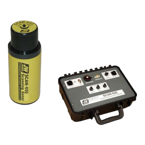
Summary of Contents for JW Fishers SCAN-650
- Page 1 SCAN-650 Scanning Sonar OPERATION MANUAL JW FISHERS MFG INC rev 811 JW FISHERS MFG INC 1953 COUNTY ST. E. TAUNTON, MA 02718 USA (508) 822-7330; (800) 822-4744; FAX (508) 880-8949 Email: jwfishers@aol.com WEB: www.jwfishers.com...
- Page 2 SCAN-650 Scanning Sonar OPERATION MAINTENANCE MANUAL Surface Sonar Processor Included JW FISHERS MFG INC 1953 COUNTY ST. E. TAUNTON, MA 02718 USA (508) 822-7330; (800) 822-4744; FAX (508) 880-8949 Email: jwfishers@aol.com WEB: www.jwfishers.com...
-
Page 3: Table Of Contents
TABLE OF CONTENTS • CAUTIONS ......................4 • SPECIFICATIONS AND OPTIONS ................ 5 • MINIMUM SYSTEM REQUIREMENTS ..............6 • INTRODUCTION ....................7 • SYSTEM COMPONENTS ..................9 • THEORY OF OPERATION .................. 11 • OPERATOR SWITCHES AND CONTROLS ............16 •... -
Page 4: Cautions
CAUTIONS: • Do not allow the SCAN-650 to be exposed to excessive heat by leaving it in direct sunlight or inside of a closed vehicle on a hot day. Excessive heat can buildup inside the housing which can damage the electronics and/or destroy the waterproof seals. -
Page 5: Specifications And Options
SPECIFICATIONS PERFORMANCE/DESCRIPTION: • Frequency ......................650 kHz. • Beamwidth - horizontal x vertical ............2.4 deg by 40 deg. • Ranges: ..................5, 10, 20, 40, 60 meters ....................16.5, 33, 66,132,198 feet • Max depth ....................300 m / 1,000 ft . •... -
Page 6: Minimum System Requirements
SCAN-650 MINIMUM SYSTEM REQUIREMENTS CPU: Intel or AMD. 500MHz System memory: 64 Mb RAM (Faster CPU and more RAM will allow faster scanning) One available USB port Windows 98 or later 15 Mb of free disk space for program installation... -
Page 7: Introduction
INTRODUCTION The SCAN-650 is a high performance imaging sonar system available in two different package configurations which enables it be used on large or small ROVs. It can also be pole-mounted and used from a small boat in shallow water. - Page 8 The most common application is mounting the scanning head on an ROV. The ROV can rest on the bottom or hover just off the bottom and the sonar scans 360 degrees looking for targets. SCAN-650 scanning head mounted on Fishers SeaLion ROV.
-
Page 9: System Components
SYSTEM COMPONENTS Signals from the scanning head travel up the cable to the Sonar Processor on the surface. The signals are processed and sent to the PC where the signal is displayed and recorded. The boat’s GPS receiver can also be connected to the Sonar Processor. If connected, the boat’s Latitude and Longitude will be displayed and recorded by the PC. - Page 10 LEFT BLANK...
-
Page 11: Theory Of Operation
The fact that scanning sonar sweeps the beam back and forth across the bottom gives a major improvement over the depth sounder printout for bottom detail. Not only can very small targets be detected but the details of the target can be seen. Signal SCAN-650 Signal SCAN-650 Top View (very narrow signal) - Page 12 THEORY OF OPERATION (continued) The JW Fishers SCAN-650 scanning sonar operates by transmitting a short, high energy, narrow width acoustic wave. This high energy acoustic wave hits directly below the transducer first (as shown below) Fish Transducer Acoustic Wave 100 m Range Switch...
- Page 13 “degrees per step” sector. 0 deg Screen View Single line displayed on the screen. SCAN-650 The width of this sector is determined 270 deg 90 deg by the “Degrees per Step” setting.
- Page 14 TIME VARIABLE GAIN (TVG) The Sonar Processor contains a TVG circuit on the PC board that receives the echo signals from the fish preamplifier boards. The TVG circuit amplifies and makes time variable gain adjustments to the signal to make up for signal losses which occur when the echoes are traveling through the water;...
- Page 15 The TVG amplifier has three operator controls. They are located on the top panel of the Sonar Processor. Recommended settings for the TVG controls are provided in the Operation Section of this manual. Final TVG adjustments are made by the operator while the unit is running. The function of these controls is to adjust the amplifiers to compensate for losses that occur when the signal travels through the water.
-
Page 16: Operator Switches And Controls
SONAR PROCESSOR Computer: The system will run on a Laptop, Desktop, or on JW Fishers optional “Splash Proof” computer. The “Splash Proof” is a computer system that is built into a Underwater Kinetics case. It utilizes a 10” Ultra Bright” display which is much easier to read in a open boat.The Sonar Processor has an integrated interface board that converts the analog signals to digital, and inputs the signal to the computer. - Page 17 • POWER INPUT - The power input for the Sonar Processor can be any voltage between 9 and 12 volts dc. A wall transformer is also supplied with the SCAN-650 which allows the Sonar Processor to be powered from 120/220 volts ac. The wall transformer converts 120/220 volts ac to 12 volts dc.
- Page 18 • Open file - Use this to open an existing sonar file for playback. • Save screen as a picture - Saves the image on the sonar screen as a Bitmap file. • Print screen - Prints the image shown on the screen. • Exit - closes the SCAN-650 program.
- Page 19 OPERATOR SWITCHES AND CONTROLS (continued) View: The number of toolbars available under VIEW depends on the display resolution selected for the monitor. The higher resolution settings permit a single large toolbar (Mode/Screen Toolbar), where a lower resolution setting (640 by 480) requires three toolbars (Standard/Playback/Screen Position) to show the same number of icons.
- Page 20 OPERATOR SWITCHES AND CONTROLS (continued) separate file (see page 24 for details). Settings: • Set Serial Port number - The Sonar Processor has an integrated USB to Serial communications port. The operator must select the Sonar Processor com port for proper operation. Note: Use the same physical USB port on the PC every time.
- Page 21 OPERATOR SWITCHES AND CONTROLS (continued) TOOL BARS: Mode/Screen Toolbar- The Mode/Screen toolbar allows for easy 1-click access to many software functions. A “Tooltip” stating the name of a button will appear when the mouse cursor hovers over the button . These controls are duplicates of “Menu”...
- Page 22 The speed can be adjusted from very slow to very fast. Sweep speed bar - Only needed if your SCAN-650 Sonar Processor connects to your PC using a PC-CARD. If your Sonar Processor connects to your PC using a USB port, the Sweep Speed Bar is not used [speed adjustment is automatic].
- Page 23 OPERATOR SWITCHES AND CONTROLS (continued) TOOLBARS: (CONTINUED) Settings Toolbar Displayed on the right side of the screen. Information and pull down menus are: - Range - The range setting sets the radius of area to be scanned. Range settings of: 5, 10, 20, 40, or 60 meters are available. A 360° sweep with a range setting of 10 meters would result in a total scan diameter of 20 meters.
- Page 24 - Run Time - Shows the running time of the sonar. This is the time from when the SCAN-650 application is opened, or a new recording is started. - Time - Shows the time of day (gets the info from the computer). Under Settings (top toolbar), 12 hr or 24 hr clock can be selected.
- Page 25 OPERATOR SWITCHES AND CONTROLS (continued) SCREEN POSITION (under the View Menu and Mode/Screen Toolbar) The operator can move the origin point (center) of the sweep to any position on the screen to give a large viewing area. Moving the origin point and increasing the zoom extends the image from the top to the bottom of the screen.
- Page 26 Size (Located in the Settings Toolbar) Allows the operator to measure the size of any object shown on the sonar display, measure the distance between objects or the distance between the object tnd the tranducer. A “Size” can be measured by: 1.
-
Page 27: Installing Hardware And Software
Interface board (analog to digital board). The second program is a USB to Serial Driver. This pro- gram is required for the PC to control the Sonar Processor Settings. The third program, SCAN-650, is the actual operating software. All Software must be installed before the Sonar Processor is con- nected to the computer with the included USB cable. - Page 28 13. A messagebox will appear stating ‘You must restart your computer for the con- figuration changes made by JW Fishers SCAN-650 to take effect. Click on ‘Yes, I want to restart my computer now’ and ‘OK’ to complete the InstaCal installation.
- Page 29 If you are using your own computer system then proceed below. (If your SCAN-650 connects to your PC using a PC-CARD or PCI board (desktop PC) skip to page 26) When you first connect the Sonar Processor SP to PC Interface (USB Cable), the Windows “Found New Hardware Wizard will launch.
- Page 30 For PCI board (Desktop PC) Before the SCAN-650 can be used for the first time, this program must be run to configure and calibrate the Interface board. This program will also need to be run if the Interface board has been removed and replaced in the PC or moved to a different slot on the motherboard.
-
Page 31: Cabling The System
INSTALLING HARDWARE AND SOFTWARE (continued) When you run the SCAN-650 software for the first time it will be necessary to configure the SCAN-650 software to open the correct COM (serial) port for communications. To select the COM (serial)port number that the software will use: 1. -
Page 32: Attaching To Rov
4.) Boot you PC into Windows. Wait until Windows is fully loaded before proceeding. 5.) Switch the Sonar Processor Power Switch ‘ON’ 6.) Attach the (USB) interface cable that connects the Sonar Processor to the PC 7.) Launch the SCAN-650 Application USB Interface Cable... - Page 33 CONNECTING THE CABLES (PC-CARD or PCI for Desktop PC) The drawing below shows the cable connections between the Scanning Head, the Sonar Processor, the boat’s GPS system, and the PC. See pages 9 and 10 of this maual for a description and picture of each of the cables. Scanning Head Interface PC (customer supplied)
- Page 34 ATTACH THE SCANNING HEAD TO ROV OR POLE HANDLE After attaching the SCAN-650 cables to the appropriate system components, the Scanning Head can be attached to the ROV or mounted on a pole handle for operation from a boat. When attaching the Scanning Head to an ROV, if the Head and Electronics are in one unit, mount the unit on the top of the ROV.
-
Page 35: Operation
GPS. 4. Turn on the PC. If the SCAN-650 is being operated for the first time, the Interface board must be installed into the computer and the SCAN-650 software loaded onto the hard disk. -
Page 36: Sample Playback
To playback a sample file follow the steps below. 1. Open the SCAN-650 program. Under the File heading on the toolbar click Open. Select the sample file from the sample file stored on the hard disk. The default location of the sample files is: C:\Program Files\JW Fishers\SCAN-650\Sample Data Files 2. -
Page 37: Sample Recording
The complete system needs to be cabled up and ready to go with the SCAN-650 deployed on an ROV or on a pole over the side of a boat (3-4 ft off the bottom). 1. Open the Scan-650 application. - Page 38 9. The SCAN-650 is now ready to begin displaying and recording sonar data. To record a new file click the red button at the top of the left side toolbar or click ”Actions” on the top toolbar and select “Record”. Before the recording begins, you will be asked to name the file and select a location for the storage.
-
Page 39: Faqs
How do I adjust to compensate for a bottom that slopes away or towards the scanner head? The SCAN-650 produces a fan shaped beam that is 40 degrees in the vertical plane. This allows the SCAN-650 to scan gently sloped bottoms without altering the orientation of the scan- ning head. - Page 40 SCAN-650. Lowering the SCAN-650 to the bottom of a lake or pond on a self leveling tripod ensures the scanning head is perpendicular to the bottom and in the proper position for scanning a fairly level bottom (as is common in most ponds).
-
Page 41: Troubleshooting
The JW Fishers Sonar requires a COM (serial) port to pass operation parameters from the PC to the Sonar. It will be necessary to configure the JW Fishers Sonar software to open the correct COM (serial) port for communications. Below are instructions for configuring the COM (serial) port. - Page 42 The driver software for this interface board is installed as part of the JW Fishers Sonar application installation process. After the JW Fishers Sonar application installation process is completed and before the sonar system is run for the first time, a program to configure the interface board must be run.
- Page 43 The latest version of software has improved performance and should allow faster sweep speeds. A new version of the SCAN-650 software is available for download. The latest version of software offers improved performance and fixes several minor bugs found in earlier revisions.
-
Page 44: Appendix A (Configuring Gps)
If, after selecting a revision, either the position or heading is missing, try selecting another revision. Baud rate – The SCAN-650 uses the industry standard speed of 4800 baud for the NMEA 0183 interface. If your receiver offers a selection of alternate baud rates, select... -
Page 45: Appendix B (Usb To Serial Adaptor)
APPENDEX B USB TO SERIAL ADAPTOR Windows XP 1. Load the driver software for the USB to Serial Adapter. Follow the manufacturers instructions. Leave the adapter connected to the PC. Skip this step if it has already been done. Complete the following steps to open the ‘Device Manager’ on your PC. These steps are necessary to find out what ‘Com Port Number’... - Page 46 Port (COM6)’ or ‘Prolific USB to Serial Com Port (COM4)’. Make note of the COM number; you will need it when operating the SCAN-650 software. Click on this item. 6. When the ‘Properties’ window opens, select the ‘Port Settings’ tab.
-
Page 47: Maintenance
The system is warranted for TWO FULL YEARS from the date of purchase. During this period the SCAN-650 will be repaired free of charge should a failure occur due to materials or workmanship under normal use.
Need help?
Do you have a question about the SCAN-650 and is the answer not in the manual?
Questions and answers