Table of Contents
Advertisement
TABLE OF CONTENTS
1 Safety Precautions----------------------------------------------- 3
2 Specifications ----------------------------------------------------- 5
2.1. CS-C18HKQ CU-C18HKQ ------------------------------ 5
2.2. CS-C24HKQ CU-C24HKQ ------------------------------ 7
3 Features ------------------------------------------------------------- 9
4 Location of Controls and Components ------------------10
4.1. Product Overview-----------------------------------------10
5 Dimensions--------------------------------------------------------11
5.1. Indoor Unit & Remote Control ------------------------- 11
5.2. Outdoor Unit -----------------------------------------------12
6 Refrigeration Cycle Diagram --------------------------------13
7 Block Diagram----------------------------------------------------14
8 Wiring Connection Diagram ---------------------------------15
8.1. CS-C18HKQ CU-C18HKQ -----------------------------15
8.2. CS-C24HKQ CU-C24HKQ -----------------------------16
9 Electronic Circuit Diagram -----------------------------------17
10 Printed Circuit Board-------------------------------------------18
10.1. Indoor Unit--------------------------------------------------18
10.2. Power Printed Circuit Board ---------------------------20
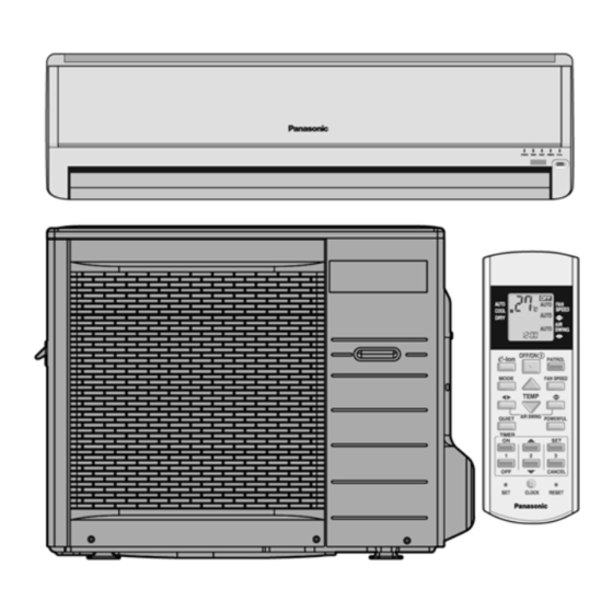
Indoor Unit Outdoor Unit
CS-C18HKQ CU-C18HKQ
CS-C24HKQ CU-C24HKQ
PAGE
10.3. Indicator ---------------------------------------------------- 21
11 Installation Instruction ---------------------------------------- 22
11.1. Select the Best Location ------------------------------- 22
11.2. Indoor Unit ------------------------------------------------- 23
11.3. Outdoor Unit----------------------------------------------- 25
12 Operation Control----------------------------------------------- 28
12.1. Cooling Operation---------------------------------------- 28
12.2. Soft Dry Operation --------------------------------------- 29
12.3. Automatic Operation ------------------------------------ 30
12.4. Indoor Fan Speed Control ----------------------------- 31
12.5. Outdoor Fan Speed Control --------------------------- 32
12.6. Vertical Airflow Direction Control --------------------- 33
12.7. Horizontal Airflow Direction Control ----------------- 33
12.8. Powerful Operation -------------------------------------- 34
12.9. Quiet Operation------------------------------------------- 35
12.10. Timer Control---------------------------------------------- 35
12.11. Random Auto Restart Control ------------------------ 36
12.12. Remote Control Signal Receiving Sound ---------- 36
12.13. Patrol Operation ------------------------------------------ 37
© 2007 Panasonic HA Air-Conditioning (M) Sdn. Bhd.
(11969-T). All rights reserved. Unauthorized copying
and distribution is a violation of law.
Order No. MAC0710041C3
Air Conditioner
PAGE
Advertisement
Table of Contents

Related Manuals for Panasonic CS-C18HKQ


Summary of Contents for Panasonic CS-C18HKQ
-
Page 1: Table Of Contents
12.12. Remote Control Signal Receiving Sound ---------- 36 10.2. Power Printed Circuit Board ---------------------------20 12.13. Patrol Operation ------------------------------------------ 37 © 2007 Panasonic HA Air-Conditioning (M) Sdn. Bhd. (11969-T). All rights reserved. Unauthorized copying and distribution is a violation of law. - Page 2 12.14. e-ion Operation ------------------------------------------- 40 13 Protection Control ---------------------------------------------- 43 13.1. Restart Control (Time Delay Safety Control) ------ 43 13.2. 7 Minutes Time Save Control ------------------------- 43 13.3. 60 Seconds Forced Operation ------------------------ 43 13.4. Starting current Control --------------------------------- 43 13.5.
-
Page 3: Safety Precautions
1 Safety Precautions • Read the following “SAFETY PRECAUTIONS” carefully before perform any servicing. • Electrical work must be installed or serviced by a licensed electrician. Be sure to use the correct rating of the power plug and main circuit for the model installed. •... - Page 4 1. Do not install the unit at place where leakage of flammable gas may occur. In case gas leaks and accumulates at surrounding of the unit, it may cause fire. 2. Carry out drainage piping as mentioned in installation instructions. If drainage is not perfect, water may enter the room and damage the furniture.
-
Page 5: Specifications
2 Specifications 2.1. CS-C18HKQ CU-C18HKQ Item Unit Indoor unit Outdoor unit Performance Test Condition NEW JIS Capacity 5.30 BTU/h 18100 *kJ/h 19080 3.06 kJ/hW 11.02 Noise Level dB (A) High: 42 Low: 37 High: 55 / - Power level dB —... - Page 6 Item Unit Power Source (Phase, Voltage, Cycle) ø Single Input power 1.73k Starting Current Running Current Cooling Maximum Current Cooling 10.6 Power Factor Cooling Power factor means total figure of compressor, indoor fan motor and outdoor fan motor. Power Cord Number of core 3 (1.5mm) Length...
-
Page 7: Cs-C24Hkq Cu-C24Hkq
2.2. CS-C24HKQ CU-C24HKQ Item Unit Indoor unit Outdoor unit Performance Test Condition NEW JIS Capacity 7.03 BTU/h 24000 *kJ/h 25310 2.72 kJ/hW 9.81 Noise Level dB (A) High: 46 Low: 40 High: 56 / - Power level dB — — Moisture Removal (pt/h) Air Volume... - Page 8 Item Unit Power Source (Phase, Voltage, Cycle) ø Single Input power 2.58 Starting Current Running Current Cooling 11.7 Maximum Current Cooling 14.3 Power Factor Cooling Power factor means total figure of compressor, indoor fan motor and outdoor fan motor. Power Cord Number of core 3 (2.5mm) Length...
-
Page 9: Features
3 Features • E-ion Air Purifying System with Patrol Sensor - Active e-ions are released to catch dust particles and bring them back the large positively charged filter - Patrol Sensor color changes to indicate the dirt level in the air •... -
Page 10: Location Of Controls And Components
4 Location of Controls and Components 4.1. Product Overview 4.1.1. Indoor Unit 4.1.2. Outdoor Unit 4.1.3. Remote Control... -
Page 11: Dimensions
5 Dimensions 5.1. Indoor Unit & Remote Control 5.1.1. CS-C18HKQ CS-C24HKQ... -
Page 12: Outdoor Unit
5.2. Outdoor Unit 5.2.1. CU-C18HKQ CU-C24HKQ... -
Page 13: Refrigeration Cycle Diagram
6 Refrigeration Cycle Diagram... -
Page 14: Block Diagram
7 Block Diagram... -
Page 15: Wiring Connection Diagram
8 Wiring Connection Diagram 8.1. CS-C18HKQ CU-C18HKQ Resistance of Outdoor Fan Motor Windings Resistance of Compressor Windings MODEL CU-C18HKQ MODEL CU-C18HKQ CONNECTION CWA951401J CONNECTION 2K25S236F6A BLUE-YELLOW 59.47 C - R 1.505 YELLOW-RED 60.95 C - S 1.809 Note: Resistance at 20 C of ambient temperature. -
Page 16: Cs-C24Hkq Cu-C24Hkq
8.2. CS-C24HKQ CU-C24HKQ Resistance of Outdoor Fan Motor Windings Resistance of Compressor Windings MODEL CU-C24HKQ MODEL CU-C24HKQ CONNECTION CWA951399J CONNECTION 2J39S236A1A BLUE-YELLOW 59.47 C - R 0.933 YELLOW-RED 60.95 C - S 1.584 YELLOW-ORANGE 80.58 Note: Resistance at 20 C of ambient temperature. Note: Resistance at 20 C of ambient temperature. -
Page 17: Electronic Circuit Diagram
9 Electronic Circuit Diagram... -
Page 18: Printed Circuit Board
10 Printed Circuit Board 10.1. Indoor Unit TOP VIEW... - Page 19 BOTTOM VIEW...
-
Page 20: Power Printed Circuit Board
10.2. Power Printed Circuit Board TOP VIEW BOTTOM VIEW... -
Page 21: Indicator
10.3. Indicator TOP VIEW BOTTOM VIEW... -
Page 22: Installation Instruction
11 Installation Instruction 11.1. Select the Best Location 11.1.3. Indoor/Outdoor Unit Installation Diagram 11.1.1. Indoor Unit • There should not be any heat source or steam near the unit. • There should not be any obstacles blocking the air circulation. •... -
Page 23: Indoor Unit
11.2. Indoor Unit 11.2.1. How to Fix Installation Plate 11.2.2. To Drill a Hole in the Wall and Install The mounting wall is strong and solid enough to prevent it from a Sleeve of Piping the vibration. 1. Insert the piping sleeve to the hole. 2. - Page 24 3. For the embedded piping (This can be used for left rear piping and left bottom piping also.)
-
Page 25: Outdoor Unit
11.2.4. Connect the Cable to the Indoor Unit 1. The inside and outside connecting cable can be connected without removing the front grille. 2. Connecting cable between indoor unit and outdoor unit shall be approved polychloroprene sheathed 3 2.5 mm flexible cord, type designation 245 IEC 57 or heavier cord. -
Page 26: Connecting The Piping
11.3.2. Connecting the Piping Connecting The Piping To Indoor Unit Please make flare after inserting flare nut (locate at joint portion of tube assembly) onto the copper pipe. (In case of using long piping) Connect the piping • Align the center of piping and sufficiently tighten the flare nut with fingers. -
Page 27: Connect The Cable To The Outdoor Unit
<For the left pipings> 1) Measure the pressure. 2) Keep it for 5-10 minutes Ensure if the pressure indicated on the gauge is as same as that of measured at first time. 2) Air purging The air remaining in the Refrigeration cycle which contains moisture may cause malfunction on the Compressor. -
Page 28: Operation Control
12 Operation Control 12.1. Cooling Operation • Cooling operation can be set using remote control. • This operation is applied to cool down the room temperature reaches the setting temperature set on the remote control. • The remote control setting temperature, which takes the reading of intake air temperature sensor, can be adjusted from 16 C to 30 C. -
Page 29: Soft Dry Operation
12.2. Soft Dry Operation • Soft Dry operation can be set using remote control. • Soft Dry operation is applied to dehumidify and to perform a gentle cooling to the room. • This operation starts when the intake air temperature sensor reaches the setting temperature on the remote control. •... -
Page 30: Automatic Operation
12.3. Automatic Operation • Automatic operation can be set using remote control. • This operation starts to operate with indoor fan at SLo speed for 25 seconds to judge the intake air temperature. • After judged the temperature, the operation mode is determined by referring to the below standard. •... -
Page 31: Indoor Fan Speed Control
12.4. Indoor Fan Speed Control • Indoor Fan Speed can be set using remote control. 12.4.1. Fan Speed Rotation Chart Fan Speed (rpm) COOL/DRY CS-C18HKQ CS-C24HKQ S Hi 1420 1590 1360 1500 1250 1390 H Lo 1220 1330 C Lo... -
Page 32: Outdoor Fan Speed Control
• Auto Fan Speed during Cooling operation: 1. Indoor fan will rotate alternately between off and on as shown in below diagram. 2. At the beginning of each compressor start operation, indoor fan will increase fan speed gradually for deodorizing purpose. 3. -
Page 33: Vertical Airflow Direction Control
12.6. Vertical Airflow Direction Control 12.6.1. Auto Control • When the vertical airflow direction is set to Auto using the remote control, the louver swings up and down as shown in the diagram. • When stopped with remote control, the discharge vent is reset, and stop at the closing position. •... -
Page 34: Powerful Operation
12.7.2. Manual Control • When the horizontal airflow direction is set to Manual using the remote control, the automatic airflow is released and the airflow direction vane move left and right in the range shown in the diagram. The louver can be adjusted by pressing the button to the desired vane position. •... -
Page 35: Quiet Operation
12.9. Quiet Operation (For Cooling Operation or cooling region of Soft Dry Operation) • To provide quiet cooling operation condition. • Once the Quiet Mode is set at the remote control, the Quiet Mode LED illuminated. The sound level will reduce around 2 dB (A) for Lo fan speed or 3 dB(A) for Hi/Me fan speed against the present operation sound level. -
Page 36: Random Auto Restart Control
12.10.2. OFF Timer • When the OFF Timer is set by using the remote control, the unit will stop operate according to the desired setting. Notes 1. By pressing ON/OFF operation button, the ON Timer or OFF Timer setting will not be cancelled. 2. -
Page 37: Patrol Operation
12.13. Patrol Operation • To monitor air dirtiness level by using Patrol sensor and to maintain air freshness by activates e-ion operation. • Patrol operation start condition - When the unit operation is started with “OFF/ON” button. - When the unit stops, “Patrol” button is pressed, Patrol individual operation will start. - During cooling only operation, “Patrol”... - Page 38 • Patrol Sensor Control - First 2 minutes from Patrol function activates is stabilization time, during stabilization time, no air dirtiness level is monitored. The Air Dirtiness level is set to Clean, Patrol LED turns blue color. - After that, Patrol sensor starts to record the resistance value at fixed interval. Higher resistance value indicates cleaner air. - The air dirtiness level is monitored by comparing the current resistance value with maximum resistance value from time to time to get the Air Dirtiness Value.
- Page 39 • Airflow direction (Horizontal, Vertical) Control - During any operation mode combines with Patrol operation, airflow direction follows respective operation mode. - During Patrol individual operation if e-ion starts, only Auto Air Swing is allowed. Even if “Air Swing” button is pressed, no signal is sent to air conditioner, and no change on LCD display.
-
Page 40: E-Ion Operation
12.14. e-ion Operation • This operation provides clean air by producing negative ions to attract dust captured at the positively charged e-ion filters. • e-ion operation start condition - During unit running at any operation mode, if “e-ion” button is pressed, combination operation (operation mode + e-ion operation) starts. - Page 41 • Airflow direction control - During any operation mode combines with e-ion operation, airflow direction follows respective operation mode. - During e-ion individual operation, only Auto Air Swing is allowed. Even if Air Swing button is pressed, no signal is sent to air conditioner, and no change on LCD display.
- Page 42 • Error Detection Control When e-ion indicator blink, it indicates error listed below: 1. e-ion AIR PURIFYING SYSTEM PCB main connector open: • Judgment Method - During e-ion operation (include during Patrol operation), e-ion AIR PURIFYING SYSTEM main connector to PCB is opened.
-
Page 43: Protection Control
Protection Control 13.1. Restart Control (Time Delay Safety Control) • When the thermo-off temperature (temperature which compressor stops to operate) is reached during:- - Cooling operation - the compressor stops for 3 minutes (minimum) before resume operation. - Soft Dry operation - the compressor stops for 6 minutes (minimum) before resume operation. •... -
Page 44: Compressor Reverse Rotation Protection Control
13.6. Compressor Reverse Rotation Protection Control • If the compressor is operating continuously for 5 minutes or longer and the temperature difference between intake air and indoor heat exchanger is 2.5 C or less for continuous 2 minutes, compressor will stop and restart automatically. •... -
Page 45: Servicing Mode
14 Servicing Mode 14.1. Auto OFF/ON Button 1. AUTO OPERATION MODE The Auto operation will be activated immediately once the Auto OFF/ON button is pressed. This operation can be use to operate air conditioner with limited function if remote control is misplaced or malfunction. 2. -
Page 46: Remote Control Button
14.3. Remote Control Button 14.3.1. SET BUTTON • To check current remote control transmission code. - Press for more than 10 seconds. • To change the air quality sensor sensitivity: - Press and release with pointer. - Press the Timer Decrement button to select sensitivity: 1. -
Page 47: Troubleshooting Guide
15 Troubleshooting Guide 15.1. Refrigeration cycle system In order to diagnose malfunctions, make sure that there are no electrical problems before inspecting the refrigeration cycle. Such problems include insufficient insulation, problem with the power source, malfunction of a compressor and a fan. The normal outlet air temperature and pressure of the refrigeration cycle depends on various conditions, the standard values for them are shown in the table to the right. -
Page 48: Diagnosis Methods Of A Malfunction Of A Compressor
15.1.1. Relationship between the condition of the air conditioner and pressure and electric current Cooling Mode Condition of the air conditioner Low Pressure High Pressure Electric current during operation Insufficient refrigerant (gas leakage) Clogged capillary tube or Strainer Short circuit in the indoor unit Heat radiation deficiency of the outdoor unit Inefficient compression... -
Page 49: Disassembly And Assembly Instructions
16 Disassembly and Assembly Instructions WARNING • Cautions! When handling electronic controller, be careful of electrostatic discharge. • Be sure to return the wiring to its original position. • There are many high voltage components within the heat sink cover so never touch the interior during operation. Wait at least two minutes after power has been turned off. -
Page 52: Indoor Fan Motor And Cross Flow Fan Removal Procedures
16.2. Indoor Fan Motor and Cross Flow Fan Removal Procedures... -
Page 54: Technical Data
17 Technical Data 17.1. Thermostat Characteristics Cooling Soft Dry... -
Page 55: Operation Characteristics
17.2. Operation Characteristics 17.2.1. CS-C18HK CU-C18HK... - Page 57 17.2.2. CS-C24HK CU-C24HK...
-
Page 59: Exploded View And Replacement Parts List
18 Exploded View and Replacement Parts List 18.1. Indoor Unit Note: The above exploded view is for the purpose of parts disassembly and replacement. The non-numbered parts are not kept as standard service parts. - Page 60 REF. NO. PART NAME & DESCRIPTION QTY. CS-C18HKQ CS-C24HKQ CHASSY COMPLETE CWD50C1520 FAN MOTOR, DC 30W 3PH ARW61E8P30AC ARW51H8P30AC CROSS FLOW FAN COMPLETE CWH02C1010 SCREW - CROSS FLOW FAN CWH551146 BEARING ASS’Y CWH64K007 EVAPORATOR CO. CWB30C2150 CWB30C2149 FLARE NUT (1/4”) CWT251026 FLARE NUT (1/2”) (5/8”)
-
Page 61: Outdoor Unit
18.2. Outdoor Unit Note: The above exploded view is for the purpose of parts disassembly and replacement. The non-numbered parts are not kept as standard service parts. - Page 62 REF. NO. PART NAME & DESCRIPTION QTY. CU-C18HKQ CU-C24HKQ CHASSY ASS’Y CWD50K2115 CWD50K2100 COMPRESSOR 2K25S236F6A 2J39S236A1A ANTI - VIBRATION BUSHING CWH50055 NUT - COMPRESSOR MOUNT CWH561049 PACKING - COM.MOUNT CWB81043 CONDENSER CWB32C2228 CWB32C2229 SOUND PROOF BOARD CWH151051 FAN MOTOR BRACKET CWD541065 SCREW - FAN MOTOR BRACKET CWH551217...