Table of Contents
Advertisement
BIS VISTA Monitoring
SERVICE INFORMATION MANUAL
Bispectral Index (BIS) Monitoring System
Aspect Medical Systems, Inc.
One Upland Road
Norwood, MA 02062 USA
(Tel) 617-559-7000
(Tel) 888-BIS INDE(X) (U.S. only) Tel: +31.30.662.9140
(Fax) 617-559-7400
bis_info@aspectms.com
www.aspectmedical.com
System
Aspect Medical Systems, Inc.
Rx only
EC REP
Aspect Medical Systems International B.V.
3454 PV De Meern
Rijnzathe 7d2
The Netherlands
Fax: +31.30.662.9150
amsint@aspectms.com
0123
075-0015 1.00
Advertisement
Table of Contents
Troubleshooting

Subscribe to Our Youtube Channel
Summary of Contents for Aspect BIS VISTA
- Page 1 SERVICE INFORMATION MANUAL Aspect Medical Systems, Inc. Bispectral Index (BIS) Monitoring System Rx only EC REP Aspect Medical Systems, Inc. Aspect Medical Systems International B.V. One Upland Road 3454 PV De Meern Norwood, MA 02062 USA Rijnzathe 7d2 0123 (Tel) 617-559-7000 The Netherlands (Tel) 888-BIS INDE(X) (U.S.
- Page 3 Aspect Medical Systems. BIS VISTA, BISx and the BISx logo are trademarks of Aspect Medical Systems, Inc. Aspect, Bispectral Index, BIS, the BIS logo, and Zipprep are trademarks of Aspect Medical...
-
Page 5: Table Of Contents
ABOUT THIS MANUAL ......................VIII SAFETY PRECAUTIONS....................1-1 ..............................1-1 ARNINGS ..............................1-4 AUTIONS ............................1-6 EY TO YMBOLS BIS VISTA MONITORING SYSTEM OVERVIEW ............2-1 BIS VISTA M ................2-1 NTRODUCING THE ONITORING YSTEM .......................... 2-2 RINCIPAL OMPONENTS 2.2.1 The BIS VISTA Monitor............................ - Page 6 ........... 7-2 ONITORING YSTEM ROUBLESHOOTING ROCEDURE BIS VISTA S ..............7-4 YSTEM ESSAGES AND ORRECTIVE CTIONS SERVICING THE BIS VISTA SYSTEM................8-1 PIC........................... 8-1 EPLACING THE ..........................8-1 EPLACING THE ........................8-2 EPLACING THE ONITOR .......................... 8-3 EPLACING THE ATTERY .......................
- Page 7 Figure 3 - Rear Panel ...................... 2-3 Figure 4 - The BISx and PIC ................... 2-4 Figure 5 - The BIS VISTA System Block Diagram ............3-2 Figure 6 - The BIS VISTA Data Flow Diagram .............. 3-3 Figure 7 - Pole Clamp ..................... 4-3 Figure 8 - Schematic of Sensor Simulator Circuit............
-
Page 8: About This Manual
A spare parts and accessories list and system specifications are included. This manual is intended to be used in combination with the BIS VISTA Monitoring System Operating Manual. The BIS VISTA Monitoring System is designed and manufactured using state-of-the-art components and manufacturing processes. -
Page 9: Safety Precautions
• A NOTE provides useful information regarding a function or procedure. KEY TO SYMBOLS A key to the symbols used on the BIS VISTA Monitoring System appears at the end of this section. Warnings THE USE OF ACCESSORY EQUIPMENT NOT COMPLYING WITH THE EQUIVALENT SAFETY REQUIREMENTS OF THIS EQUIPMENT MAY LEAD TO A REDUCED LEVEL OF SAFETY OF THE RESULTING SYSTEM. - Page 10 GROUNDED OUTLET BEFORE ATTEMPTING TO OPERATE THE MONITOR. IF THE INTEGRITY OF THE EXTERNAL PROTECTIVE EARTH GROUND IS IN DOUBT, THE BIS VISTA SYSTEM SHALL BE OPERATED FROM ITS INTERNAL BATTERY POWER SOURCE ONLY. FOR BIS VISTA SYSTEMS USED OUTSIDE OF NORTH AMERICA: A HARMONIZED LINE CORD WITH CONDUCTORS HAVING A CROSS SECTIONAL AREA GREATER THAN 0.75 mm...
- Page 11 THE SENSOR MUST NOT BE LOCATED BETWEEN DEFIBRILLATOR PADS WHEN A DEFIBRILLATOR IS USED ON A PATIENT CONNECTED TO THE BIS VISTA SYSTEM. TO MINIMIZE THE RISK OF PATIENT STRANGULATION, THE PATIENT INTERFACE CABLE (PIC) MUST BE CAREFULLY PLACED AND SECURED.
-
Page 12: Cautions
Contact Aspect Medical Systems, Inc. or the local distributor for a replacement battery: Aspect part number 186-0208. All repairs to the BIS VISTA Monitoring System should be made only by a qualified Biomedical Engineering Technician or other authorized personnel. -
Page 13: D Evices
BISx may be damaged if opened. Service or repairs must be performed only by qualified biomedical technicians. The BIS VISTA system has been designed to operate with a BIS Sensor. The sensor is a silver/silver chloride electrode array that utilizes Aspect's patented Zipprep... -
Page 14: Key To Symbols
SECTION 1 SAFETY PRECAUTIONS ________________________________________________________________________ Key to Symbols Manufacturer Authorized Representative in the European Community EC REP Conformité Européenne (CE) Marking of Conformity to European Medical Device Directive. CE represents the Notified Body XXXX number Classified by Underwriters Laboratories Inc. with respect to electric shock, fire and mechanical hazards only, in accordance with UL 60601-1 and IEC60601-2-26 Recognized under the Component Recognition Program of... - Page 15 SECTION 1 SAFETY PRECAUTIONS ________________________________________________________________________ Attention, USB-A, Host. Consult Accompanying Documents USB-A Attention, USB-B function. Consult Accompanying Documents USB-B Caution: Hot Surface Alternating Current D/C Current Battery Location Reset Button Packaging Labelling: Storage Temperature Limits, Fragile, Do Not Get Wet, and This Side Up Monitor Power ON Monitor Power OFF or Standby Mode...
- Page 16 SECTION 1 SAFETY PRECAUTIONS ________________________________________________________________________ Operating on Battery No Battery is Installed in Monitor Ringing Bell Icon - Alarm Sounding Green Bell Icon - Alarms Active Yellow Bell with Dotted Line ‘X’ - Alarms Paused Red Bell with ‘X’ - Alarms Silenced A green box denotes ON or active condition.
-
Page 17: Bis Vista Monitoring System Overview
Introducing the BIS VISTA Monitoring System The BIS VISTA Monitoring System is intended for use under the direct supervision of a licensed healthcare practitioner or by personnel trained in its proper use. The BIS VISTA Monitor is intended for use on adult and pediatric patients within a hospital or medical facility providing patient care to monitor the state of the brain by data acquisition of EEG signals. -
Page 18: Principal Components
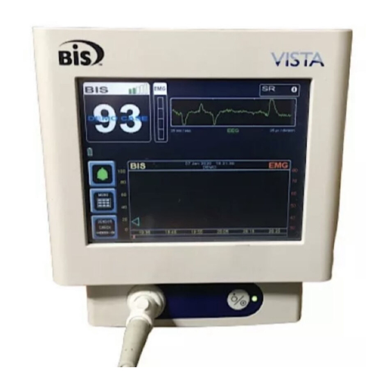
The system is composed of a monitor, a BISx, a Patient Interface Cable (PIC), and BIS sensor. 2.2.1 The BIS VISTA Monitor The front panel of the BIS VISTA monitor contains the Touch Screen, BISx port and the ON/Standby button. See Figure 2. Touch Screen The BIS VISTA monitor is designed so that all controls (with the exception of the ON/Standby button) are accessible by touching a designated area on the monitor screen. -
Page 19: Figure 3 - Rear Panel
SECTION 2 BIS VISTA MONITORING SYSTEM OVERVIEW _______________________________________________________________________ ON/Standby button The ON/Standby button is located in the lower right corner of the monitor and is used to put the monitor in ON or in Standby mode. When the small LED light to the right of the ON/Standby button is green, the unit is running and providing power to the BISx. -
Page 20: The Bisx And Patient Interface Cable (Pic)
SECTION 2 BIS VISTA MONITORING SYSTEM OVERVIEW _______________________________________________________________________ 2.2.2 The BISx and Patient Interface Cable (PIC) The BISx receives, filters, and processes patient EEG signals. It is located close to the patient's head where the EEG signal is less subject to interference from other medical equipment. -
Page 21: Proprietary Information And Devices
Systems and may not be copied, reproduced or distributed without prior written permission. Portions of the BIS VISTA Monitoring System design are proprietary and are the subject of patents and patents pending. See the BIS VISTA Operating Manual for details. - Page 22 SECTION 2 BIS VISTA MONITORING SYSTEM OVERVIEW _______________________________________________________________________...
-
Page 23: Principles Of Operation
EEG signals, digitally process the EEG data, and compute the processed parameters. The BIS VISTA monitor contains the circuits to display the waveforms and processed parameters. The PIC and BIS sensor are the patient connection for EEG signal acquisition. -
Page 24: Figure 5 - The Bis Vista System Block Diagram
PROCESSOR BOARD Reset Serial Switch Host Client Port CONNECTOR BOARD SPEAKER BACKLIGHT CARD INVERTER ENGINE MOTHER BOARD BISx DISPLAY Connector TOUCH PANEL ON/STANDBY SWITCH Power BATTERY POWER SUPPLY BIS VISTA MONITOR Figure 5 - The BIS VISTA System Block Diagram... -
Page 25: The Bisx
Host Port Port Figure 6 - The BIS VISTA Data Flow Diagram After passing through input protection circuits, the EEG signals are differentially amplified and filtered to remove DC and high frequency components. The signals are digitized by separate one bit sigma-delta analog to digital converters and sent to the Digital Signal Processor (DSP). - Page 26 SECTION 3 PRINCIPLES OF OPERATION _______________________________________________________________________ 3.2.1.1 BISx Signal Conditioning The input protection circuits are designed to protect the input from destruction by electric shock from sources such as electrostatic discharge (ESD) or defibrillation. The protection circuits also reduce the effects of high frequency ambient noise from sources such as electro- cautery and other devices.
-
Page 27: The Bis Vista Monitor
BISx circuits. 3.2.2 The BIS VISTA Monitor The BIS VISTA monitor contains the circuits to enable the touch screen, to receive processed parameters from the BISx, to display the data on the screen, and to communicate with other devices via USB and RS-232 ports. -
Page 28: The Battery
If that should occur, connect unit to wall power and press the Reset button. (Refer to Section 8.10 “Using the Reset Button”). System Features 3.3.1 System Self Checks The BIS VISTA monitor has several self-checking features to ensure that the system is operating properly. These include:... -
Page 29: Diagnostic Codes
3.3.2 Diagnostic Codes The BIS VISTA monitor provides diagnostic codes to assist the user in tracing the source of any problems that may occur. Codes are displayed in the Message Region only if the user has requested them in the Diagnostics Menu. -
Page 30: Bisx Data Memory
SECTION 3 PRINCIPLES OF OPERATION _______________________________________________________________________ 3.3.4 BISx Data Memory The BISx stores processed EEG parameters, including the BIS value, with time and date of acquisition. History data stored in the BISx can be accessed by exporting it to a removable drive using the “Export Data”... -
Page 31: Data Transfer And Software Updates
3.3.7 Data Transfer and Software Updates Three ports on the rear of the BIS VISTA monitor facilitate data transfer. The USB (Type A) port is used to export data to a removable drive. It is also used to update the monitor and BISx software. - Page 32 SECTION 3 PRINCIPLES OF OPERATION _______________________________________________________________________ 3-10...
-
Page 33: Preparation For Use And Installation
Before operation, wipe down all visible condensation and allow the system to reach equilibrium at room temperature. 4.1.2 Operating Environment The BIS VISTA Monitoring System is not designed for use in areas containing flammable gases or vapors. WARNING! -
Page 34: Power Requirements And System Grounding
360 mmHg to 800 mmHg. 4.1.3 Power Requirements and System Grounding The BIS VISTA Monitoring System requires a power source of 100-240 VAC, 50-60Hz. Current consumption is 0.7 ampere maximum. To protect operating personnel and patients, the monitor must be properly grounded. - Page 35 SECTION 4 PREPARATION FOR USE AND INSTALLATION _______________________________________________________________________ 4.1.4.1 Mounting the Monitor using the Pole Clamp To mount the monitor to a secure vertical pole (1/2" - 1½" in diameter): 1. Place pole within clamp bracket and tighten screw using the black finger knob. Make sure that there is enough space above the clamp so that you have a few inches to slide the monitor in from above.
-
Page 36: Instrument Connections
DO NOT pull apart by the cable wire. 4.2.2 Power Cord Connections The BIS VISTA Monitoring System is designed to use only 3-conductor IEC hospital-grade power cords. Cords must be type SJE, SJT, or SJO. Check for a firm connection. - Page 37 SECTION 4 PREPARATION FOR USE AND INSTALLATION _______________________________________________________________________ • Verify that light to right of ON/Standby button is yellow. 3. Start up monitor by pressing the ON/Standby button (lower right corner). • Verify that light to right of ON/Standby button is green. •...
- Page 38 SECTION 4 PREPARATION FOR USE AND INSTALLATION _______________________________________________________________________...
-
Page 39: Care And Cleaning
SECTION 5 CARE AND CLEANING _______________________________________________________________________ SECTION 5 5 CARE AND CLEANING INTRODUCTION This section describes: • Care and cleaning procedures • Preventive maintenance Care and Cleaning WARNING! UNIVERSAL PRECAUTIONS SHALL BE OBSERVED TO PREVENT CONTACT WITH BLOOD OR OTHER POTENTIALLY INFECTIOUS MATERIALS. -
Page 40: Cleaning The Monitor Display
SECTION 5 CARE AND CLEANING _______________________________________________________________________ Caution: Do not autoclave the BISx or Monitor. Autoclaving will seriously damage both components. Avoid liquid ingress to the Patient Interface Cable. Contact of fluids with the PIC sensor connectors can interfere with PIC performance. 5.1.3 Cleaning the Monitor Display Clean the monitor display screen with a mild solution of detergent and warm water or a commercial display screen cleaner, available through personal computer dealers. -
Page 41: Preventive Maintenance
_______________________________________________________________________ SECTION 6 6 PREVENTIVE MAINTENANCE INTRODUCTION The BIS VISTA system is designed so that no periodic adjustment or calibration is required. Suggested routine maintenance covered in this section includes: • Periodic checking of cable integrity • System checkout • Checking the battery •... -
Page 42: Monitor Checkout Procedure
• Verify battery icon displays below BIS number. NOTE: Since the BIS VISTA monitor has a built in battery backup, the monitor will power up with or without AC power applied. This step assures that this part of the test is performed under battery power 6. -
Page 43: Bisx Checkout Procedure
IF ANY FAILURES ARE NOTED, SEE SECTION 7.3, “BIS VISTA System Messages And Corrective Actions”. 1. Using a known good BIS VISTA monitor (see Section6.2.1 “Monitor Checkout Procedure” ), start up the monitor with the BISx disconnected. • Verify that the screen message “Connect BISx” displays. -
Page 44: Patient Interface Cable (Pic) Checkout Procedure
_______________________________________________________________________ 6.2.3 Patient Interface Cable (PIC) Checkout Procedure The successful completion of this test will verify function of the BIS VISTA system from the BISx circuits to the patient connector. Since the conductors used are located both in the BISx and the PIC, use a swapping technique to isolate the faulty component. -
Page 45: Checking The Battery
The battery must be tested periodically to verify that the BIS VISTA Monitoring System will continue to operate during power outages. To test: 1. Charge the BIS VISTA monitor by leaving it plugged into A/C power for at least 6 hours. The monitor charges while in either Standby mode (yellow light) or ON (green light). -
Page 46: Checking Leakage Current
USB ports) are separated from live parts by double insulation, a ground continuity test does not apply to these parts. The components of the BIS VISTA Monitor that are connected to protective earth are contained within its enclosure and are not accessible to the... - Page 47 Ground wire leakage typically can be performed automatically by connecting the A/C power cord of the BIS VISTA Monitor into a safety tester. The enclosure leakage may be measured by any safety test equipment that is capable of connecting to isolated conductive parts and measuring the current from those parts to earth.
- Page 48 SECTION 6 PREVENTIVE MAINTENANCE _______________________________________________________________________...
-
Page 49: Diagnostics And Troubleshooting
General Troubleshooting The BIS VISTA Monitoring System has both automatic and manual diagnostic features. These features check the BIS VISTA Monitoring System’s operability and status, and report software and hardware malfunctions. IF ANY FAILURES ARE NOTED, SEE SECTION 7.3 “BIS VISTA System Messages and Corrective Actions”... -
Page 50: Bis Vista Monitoring System Troubleshooting Procedure
The qualified user may replace the BISx cables by following the procedures in Section 8 “Servicing the BIS VISTA System.” If the cables or connectors are physically damaged, they will need to be replaced. If cables are suspect, the following may be of aid in determining which cable is defective. - Page 51 • If failure is noted, swap PIC with known good PIC cable and run again. • If failure repeats, the BISx or the BISx Bulkhead Connector is suspect. This failure may also be related to a PCB problem in the BISx in which case the BISx must be returned to Aspect for service.
-
Page 52: Bis Vista System Messages And Corrective Actions
SECTION 7 DIAGNOSTICS AND TROUBLESHOOTING ________________________________________________________________________ BIS VISTA System Messages and Corrective Actions When an alarm is triggered, a message appears in the Message Region of the screen. Possible messages and the recommended operator actions are listed below: BIS VISTA Messages and Operator Actions... - Page 53 SECTION 7 DIAGNOSTICS AND TROUBLESHOOTING ________________________________________________________________________ Status Messages: Causes: Corrective Actions: 1. At least one element of 1. Verify Sensor Check Last Sensor Check sensor has too high passes. Failed impedance, and EXIT 2. Read Instructions on pressed (before sensor sensor package and re- check completes).
- Page 54 SECTION 7 DIAGNOSTICS AND TROUBLESHOOTING ________________________________________________________________________ Status Messages: Causes: Corrective Actions: The signal quality is too low 1. If ARTIFACT label Data unavailable due to accurately calculate a BIS appears above the EEG to poor signal quality value. The BIS value and waveform box, attempt to other trend variables that identify and eliminate...
- Page 55 SECTION 7 DIAGNOSTICS AND TROUBLESHOOTING ________________________________________________________________________ Status Messages: Causes: Corrective Actions: No discernible EEG activity If unintended: Isoelectric EEG is detected for several 1. Check patient vital signs, Detected minutes; SR=100. dosage, etc. 2. Check leads for proper Note: This message connection and possible notifies user of a flatline shorts.
- Page 56 SECTION 7 DIAGNOSTICS AND TROUBLESHOOTING ________________________________________________________________________ Status Messages: Causes: Corrective Actions: 1. Poor or contaminated 1. Connect/clean connection Sensor Invalid connection between between sensor and PIC. sensor and PIC. 2. Replace the sensor. 2. Defective sensor. 3. Replace the PIC. 3.
- Page 57 SECTION 7 DIAGNOSTICS AND TROUBLESHOOTING ________________________________________________________________________ Status Messages: Causes: Corrective Actions: 6000-6999 Operating system has noted 1. Retry snapshot. Snapshot Error that the snapshot process 2. Restart monitor. has not completed correctly. 3. Reset monitor. 4. Replace monitor.
- Page 58 SECTION 7 DIAGNOSTICS AND TROUBLESHOOTING ________________________________________________________________________ 7-10...
-
Page 59: Servicing The Bis Vista System
Sections 8.12 and 8.13 for instructions on packaging and shipping. The BIS VISTA Monitoring System is designed to be easily serviced by using the built in diagnostic routines (see Section 7 “Diagnostics and Troubleshooting”) and the major component swapping techniques described below. -
Page 60: Replacing The Monitor
SECTION 8 SERVICING THE BIS VISTA MONITORING SYSTEM Replacing the Monitor Parts Required: Tools Required: BIS VISTA Monitor P/N 185-0151 None To replace the monitor: 1. Put monitor in Standby mode by pressing the ON/Standby button. The light to the right of the button should be yellow or off. -
Page 61: Replacing The Battery
Battery Replacement Kit P/N 186-0208 Philips #2 screwdriver Caution: All repairs to the BIS VISTA Monitoring System should be made only by a qualified Biomedical Engineering Technician or other authorized personnel. To replace the battery, you will need a Philips #2 screwdriver. Follow the instructions below: 1. -
Page 62: Replacing The Power Supply
Tools Required: Power Supply Replacement Kit P/N 186-0216 Philips #2 screwdriver Caution: All repairs to the BIS VISTA Monitoring System should be made only by a qualified Biomedical Engineering Technician or other authorized personnel. WARNING: POWER SUPPLY IS INTERNALLY FUSED. REPLACE POWER SUPPLY ONLY WITH ASPECT MEDICAL SYSTEMS BIS VISTA POWER SUPPLY. -
Page 63: Replacing The Clamp Shoe
To replace the Clamp Shoe, you will need Philips #2 and #8 screwdrivers. The power supply must be removed to access the Clamp Shoe screws. Follow the instructions below: 1. Unplug A/C line cord from the BIS VISTA monitor. 2. Lay the monitor screen-side-down on a scratch-free work surface so that the Battery/Power Supply cover is accessible. -
Page 64: Replacing The Monitor Interface Cable
SERVICING THE BIS VISTA MONITORING SYSTEM Replacing the Monitor Interface Cable Caution: All repairs to the BIS VISTA Monitoring System should be made only by a qualified Biomedical Engineering Technician or other authorized personnel. Use only the parts and tools specified. Use of any others may damage the instrument. - Page 65 SECTION 8 SERVICING THE BIS VISTA MONITORING SYSTEM 3. Open the ZIF connector by pulling away from the bulkhead. 4. Disconnect from the flex cable. Discard the old gasket. 5. Set the new gasket in the groove of the BISx housing.
- Page 66 SECTION 8 SERVICING THE BIS VISTA MONITORING SYSTEM ZIF open feature 6. Align the key feature on the bulkhead and the BISx unit. Attach the flex cable from the BISx to the ZIF connector on the replacement cable. ZIF closed 7.
-
Page 67: Replacing The Bisx Bulkhead Connector
8. Set the screws in the holes. Slowly tighten to 45 in-oz. Replacing the BISx Bulkhead Connector Caution: All repairs to the BIS VISTA Monitoring System should be made only by a qualified Biomedical Engineering Technician or other authorized personnel. -
Page 68: Procedure
SECTION 8 SERVICING THE BIS VISTA MONITORING SYSTEM 8.8.2 Procedure: 1. Disconnect BISx from the monitor and remove Patient Interface Cable from BISx. 2. Remove screws from the bulkhead. ZIF open 3. Open the ZIF connector by pulling away from the bulkhead. - Page 69 SECTION 8 SERVICING THE BIS VISTA MONITORING SYSTEM 4. Disconnect from the flex cable. Discard the old gasket. 5. Set the new gasket in the groove of the BISx housing. 8-11...
- Page 70 SECTION 8 SERVICING THE BIS VISTA MONITORING SYSTEM Key feature ZIF open 6. Align the key feature on the bulkhead and the BISx unit. Attach the flex cable from the BISx to the ZIF connector on the replacement bulkhead. ZIF closed 7.
-
Page 71: Calibrating The Touch Screen
“Appendix I.” 5. Perform a Patient Interface Cable (PIC) Checkout Procedure as described in Section 7.2.3. “PIC Checkout Procedure.” For more detail, refer to the BIS VISTA Monitoring System Operating Manual. 6. Perform a leakage (electrical safety test) according to the appropriate institution requirements. -
Page 72: What To Do With A Component That Requires Service
Seal the package with plastic shipping tape rather than masking tape. Mark shipping or storage container FRAGILE. • If the repair or replacement is covered by the warranty, Aspect will bear the costs of shipping the repaired or replacement product back to the user. All other shipping costs shall be paid by the user. -
Page 73: Specifications And Warranty
_______________________________________________________________________ SECTION 9 9 SPECIFICATIONS AND WARRANTY INTRODUCTION This section includes: • General specifications of the BIS VISTA monitor and accessories • Electromagnetic compatibility specifications • Warranty General Specifications This section lists specifications for the BIS VISTA Monitoring System. General Specifications:... - Page 74 SECTION 9 SPECIFICATIONS AND WARRANTY _______________________________________________________________________ EEG Specifications: Epoch Duration: 2 seconds Artifact Rejection: Automatic EEG Scales: 25 µV/div (+/- 1 mV Full Scale) EEG Sweep Speeds: 25 mm/sec Computed Parameters: Bispectral Index, Suppression Ratio, EMG, Signal Quality Index, and Burst Count User-defined Displays: Trend and real-time EEG waveforms Update Rate:...
- Page 75 SECTION 9 SPECIFICATIONS AND WARRANTY _______________________________________________________________________ BISx Specifications: BISx: Weight: 10.0 oz (0.284 kg) including integral cable Dimensions: 3.75 in wide x 2.5 in high (9.5 cm x 6.3 cm) Cable Length: 9 ft (2.7 m) Integral BISx Cable 4 ½ ft (1.4 m) from BISx to sensor connector Analog to Digital Noise-shaped sigma-delta Converter:...
- Page 76 1.1 times the highest rated AC supply voltage is applied between the applied part and earth. The circuitry inside the BIS VISTA monitor is isolated from the mains in accordance with UL60601-1. Patient isolation is accomplished within the BISx.
-
Page 77: Electromagnetic Compatibility Specifications
Electromagnetic Compatibility Specifications The BIS VISTA Monitoring System requires special precautions regarding Electromagnetic Compatibility (EMC). The BIS VISTA system must be installed and put into service according to the EMC guidance information provided in this section. Portable and mobile radio frequency communications equipment can affect the operation of the BIS VISTA Monitoring System. - Page 78 Guidance and Manufacturer’s Declaration - Electromagnetic Emissions The BIS VISTA Monitoring System is intended for use in the electromagnetic environment specified below. The customer or user of the BIS VISTA system should assure that it is used in such an environment Emissions test...
- Page 79 Guidance and Manufacturer’s Declaration - Electromagnetic Immunity The BIS VISTA system is intended for use in the electromagnetic environment specified below. The customer or user of the BIS VISTA system should assure that it is used in such an environment Immunity...
- Page 80 Guidance and Manufacturer’s Declaration - Electromagnetic Immunity The BIS VISTA Monitoring System is intended for use in the electromagnetic environment specified below. The customer or user of the BIS VISTA system should assure that it is used in such an environment. Immunity...
- Page 81 RF transmitters, an electromagnetic site survey should be considered. If the measured field strength in the location in which the BIS VISTA system is used exceeds the applicable RF compliance level above, the BIS VISTA system should be observed to verify normal operation.
- Page 82 Monitor The BIS VISTA Monitoring System is intended for use in the electromagnetic environment in which radiated RF disturbances are controlled. The customer or user of the BIS VISTA system can help prevent electromagnetic interference by maintaining a minimum distance...
-
Page 83: Warranty
Aspect. Aspect shall have no obligation to make repairs, replacements, or corrections which result, in whole or in part, from normal wear and tear. Aspect makes no warranty (a) with respect to any products that are not Warranted Products, (b) with respect to any products purchased from a person other than Aspect or an Aspect-authorized distributor or (c) with respect to any product sold under a brand name other than Aspect Medical Systems, Inc. - Page 84 SECTION 9 SPECIFICATIONS AND WARRANTY _______________________________________________________________________ THIS WARRANTY IS THE SOLE AND EXCLUSIVE WARRANTY FOR ASPECT’S PRODUCTS, EXTENDS ONLY TO THE PURCHASER, AND IS EXPRESSLY IN LIEU OF ANY OTHER EXPRESS OR IMPLIED WARRANTIES INCLUDING WITHOUT LIMITATION ANY WARRANTY AS TO MERCHANTABILITY OR FITNESS FOR A PARTICULAR PURPOSE.
-
Page 85: Accessories And Spare Parts List
186-0208 Battery Replacement Kit 186-0216 Power Supply Replacement Kit 186-0217 Shoe Clamp Replacement Kit 186-0201-AMS BIS VISTA Host Cable (Monitor Cable) Replacement Kit 195-0052 BISx Bulkhead Replacement Kit 151-0009 Battery/ Power Supply Cover Assembly with Shoe Clamp 675-0022 Cable wrap (Blue, hook & loop) 194-0039 Label “DO NOT DISCARD”... -
Page 86: Sensor Simulator: P/N: 186-0137
The Sensor Simulator is a service tool that allows for the verification of proper impedance values being detected by the BIS VISTA Monitoring System during the Sensor Check. This test is part of the initial test that each system performs. The simulator also allows for safety testing of the system in the field by allowing connection of the test equipment to the monitor via the Patient Interface Cable (PIC). -
Page 87: Test Sensor
SECTION 10 APPENDIX I _______________________________________________________________________ Figure 9 - Sensor Simulator 10.3 Test Sensor Use the following procedure to make a Test Sensor: 1. Remove a new sensor from its plastic carrier sheet and place on flat surface with the adhesive facing up. NOTE: Be careful that gel does not leak onto hands or connector during this procedure. -
Page 88: Figure 11 - Connecting Electrodes #2 And #4
SECTION 10 APPENDIX I _______________________________________________________________________ Figure 11 - Connecting electrodes #2 and #4. 3. Fold electrode #3 over onto electrode #4, pressing adhesive surfaces together and making sure the paper clip remains in place. 4. Fold electrode #1 over onto electrode #2. Figure 12 - Connecting electrode #3 with #4, and #1 with #2. -
Page 89: Safety Tester Connection With Pic
_______________________________________________________________________ 10.4 Safety Tester Connection with PIC This procedure describes a method to connect an BIS VISTA Monitoring System to a safety tester. It uses a current date sensor to provide a contact point for the safety tester leads that correspond to the patient contact points of the BIS VISTA system. -
Page 91: Data Flow Diagram
________________________________________________________________ SECTION 11 11 APPENDIX II 11.1 Data Flow Diagram Patient Input Amplification Sigma-Delta FPGA Connection Protection and Filtering Modulators Digital Serial Signal BISx Comm. Processor (DSP) BIS VISTA Monitor Serial Comm. Color Host Processor Display RS-232 Host Port Port... -
Page 92: Block Diagram
DIGITIZER P103 P102 head BOARD P101 P100 J301 J300 PROCESSOR BOARD Reset Serial Switch Host Client Port CONNECTOR BOARD SPEAKER BACKLIGHT CARD INVERTER ENGINE MOTHER BOARD BISx DISPLAY Connector TOUCH PANEL ON/STANDBY SWITCH Power BATTERY POWER SUPPLY BIS VISTA MONITOR... - Page 94 (888) BIS-INDE(X)…press (6), or (800) 442-7688 … press (6) Technical Service: (800) 442-2051 Email: bis_info@aspectms.com Web: www.aspectmedical.com Aspect Medical Systems International B.V. EC REP Rijnzathe 7d2 3454 PV De Meern The Netherlands Main Business Phone: +31.30.662.9140 Main Business Fax: +31.30.662.9150 Email: amsint@aspectms.com...
Need help?
Do you have a question about the BIS VISTA and is the answer not in the manual?
Questions and answers