Table of Contents
Advertisement
Quick Links
Advertisement
Table of Contents

Related Manuals for King Controls 9702

Summary of Contents for King Controls 9702
- Page 1 ® Automatic Satellite System 9702 9702-LP Installation and Operating Instructions Satellite Solutions for Mobile Markets 11200 Hampshire Avenue South, Bloomington, MN 55438-2453 Phone: (800) 982-9920 Fax: (952) 922-8424 www.kingcontrols.com 1347 REV M...
-
Page 2: Table Of Contents
The satellite TV market is expanding and changing. The information in this manual was accurate at the time of printing. If your King-Dome does not operate as outlined in this manual please call King Controls at (800) 982-9920 or visit our website at www.kingcontrols.com. -
Page 3: Introduction
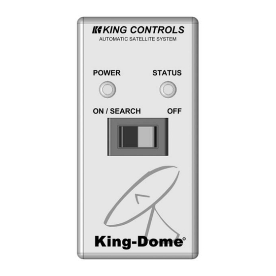
Located in the vehicle. Activates the search mode and provides limited diagnostic functions using the status light. Note: A TV, satellite receiver, and program subscription are also required for satellite TV viewing. (Not supplied by King Controls.) Fig. 1 KING CONTROLS... -
Page 4: Definition Of Terms
DEFINITION OF TERMS SECTION 2 AZIMUTH: Circular rotation around the vehicle. (like a clock face: front of vehicle is 12:00, rear is 6:00) (Fig. 2) Fig. 2 ELEVATION: Angle in degrees measured from the ground plane (Fig. 3). Fig. 3 SIGNAL STRENGTH: Intensity of electronic signal received from the satellite transmission. -
Page 5: Installation
INSTALLATION SECTION 3 TOOLS AND MATERIALS REQUIRED: - drill and drill bit set - tape measure - 7/16” open end wrench (coax connections) - adhesive sealant (compatible with roof material) - appropriate fasteners to install all components and wiring - 5/32” allen wrench, channel lock or pliers (to remove shipping bolt) - wire cutter (to remove shipping tie strap) KIT CONTENTS: 1. -
Page 6: Installation
IMPORTANT! The tie strap and spacer, and the bolt and washer must be removed from the bottom of the dome unit prior to installation. DO NOT REMOVE THE DOME COVER TO REMOVE THESE SHIPPING RESTRAINTS. YOU MUST PLUG THE SHIPPING BOLT HOLE WITH THE SUPPLIED PLUG. 2. - Page 7 DOME LOCATION 4. Select an area on the roof for the dome unit and the location where the wiring will enter the vehicle through the roof to the satellite receiver, controller, and 12 volt power source inside, using the following criteria: a) The shortest distance between the dome unit and the satellite receiver is most desirable.
- Page 8 Fig. 7 Example of truck installation using bracket. See bracket instructions for proper installation. IMPORTANT! The dome unit MUST be mounted to the air ride cab: NEVER to any structure mounted directly to the frame. DOME INSTALLATION IMPORTANT! Make sure shipping restraints are removed from bottom of dome unit (Fig.
- Page 9 Note: The installer is responsible for determining the most appropriate fastener to secure the dome to the roof. Depending on the roof material, fasteners such as lag screws, well nuts, sheet metal screws, toggle bolts and T anchors may be used, and should always be used in combination with a roof compatible sealant.
- Page 10 11. Run wires from the back of the dome unit to the roof edge, then along edge to location where wiring will be fed into the vehicle. (If installing an optional second receiver, run auxiliary coax to location where it will enter the vehicle.) Secure wiring to roof every 12- 18 inches (Fig.
- Page 11 INTERNAL WIRING IMPORTANT: The connection between the dome unit and the receiver must be a direct connection with no devices in between. Any other devices should be downstream from the receiver. 14. Inside vehicle, connect main coax from the dome unit directly to the “satellite in” port of the main receiver.
- Page 12 16 times: programs in 47 degree elevation rapidly flashes red and green 20 times: programs in 55 degree elevation rapidly flashes red and green (9702-LP ONLY) Press ON/SEARCH and HOLD for 3 seconds. Turns momentarily orange, then back to red or green Press OFF.
-
Page 13: Operation
Hand Held Wall Mount ON/SEARCH for 4 SECONDS. Power light Controller Controller turns steady GREEN. STATUS LIGHT SYSTEM STATUS King Controls KING-DOME unit performs a) flashes a variety of colors ON/SEARCH STATUS for about one minute self-diagnostic search in progress... -
Page 14: Multi-Switch
MULTI-SWITCH SECTION 5 (WALL MOUNT ONLY) FOR DISH 500 SUBSCRIBERS After you have locked onto the 110 or 119 satellite using the operation procedure in Section 4, you can use the Wall Mount Multi-Switch Controller to move back and forth between the 110 and 119 satellites. -
Page 15: Troubleshooting
4 SECONDS. button for a full 4 and/or green.) seconds. STATUS light blinks orange. Before search: bad coax Call King Controls connection After unsuccessful search Move vehicle to have (approximately 25 minutes): unobstructed view of obstruction in line of sight... -
Page 16: Maintenance
If you have any comments or questions, please contact the King Controls Service Department at (800) 982-9920, or email King Controls at info@kingcontrols.com... -
Page 17: Limited Warranty
- The product has been abused, misused, improperly installed or improperly maintained. - Repairs have been made or attempted by others that are not certified by King Controls to do such repairs. - Repairs are required because of normal wear and tear. - Page 18 ® 11200 Hampshire Avenue South, Bloomington, MN 55438-2453 Phone: (800) 982-9920 Fax: (952) 922-8424 www.kingcontrols.com...
Need help?
Do you have a question about the 9702 and is the answer not in the manual?
Questions and answers