Table of Contents
Advertisement
Advertisement
Table of Contents

Related Manuals for Excalibur CTEX-21CE

Summary of Contents for Excalibur CTEX-21CE
- Page 2 Head tilts 45° left and right. 21" Throat capacity. 2" Cutting thickness capacity. Large 13 1/2” x 23 1/2” ( 345mm x 597 mm) table surface. Finger operated blade clamps, no tools required. Easy access speed and tension controls. Organized blade storage on base. Unique tilting head design tilts the blade, not the table keeping the workpiece level for better control &...
- Page 3 Once you’ve read through these instructions, keep this manual handy for future reference. GENERAL® INTERNATIONAL WARRANTY All component parts of Excalibur by General® International products are carefully tested and inspected during all stages of production, and each unit is thoroughly inspected upon completion of assembly. Because of our commitment to quality and customer satisfaction, General®...
-
Page 4: Rules For Safe Operation
Rules for Safe Operation To help ensure safe operation, please take a moment to learn the machine’s applications and limita- tions, as well as potential hazards. General® International disclaims any real or implied warranty and hold itself harmless for any injury that may result from the improper use of its equipment. 1. -
Page 5: Additional Safety Instructions
Additional Safety Instructions Specific to this Scroll Saw Because each shop situation is unique, no list of safety guidelines can ever be complete. The most important safety feature in any shop is the knowledge and good judgement of the user. Use common sense and always keep safety considerations, as they apply to your individual shop situation first and foremost in mind. -
Page 6: Electrical Requirements
ELECTRICAL REQUIREMENTS Before connecting the machine to the power source, verify that the voltage of your power supply corresponds with the voltage specified on the motor I.D. nameplate. A power source with greater voltage than needed can result in serious injury to the user as well as damage to the machine. If in doubt, contact a qualified electrician before con- necting to the power source. -
Page 7: Identification Of Main Parts And Components
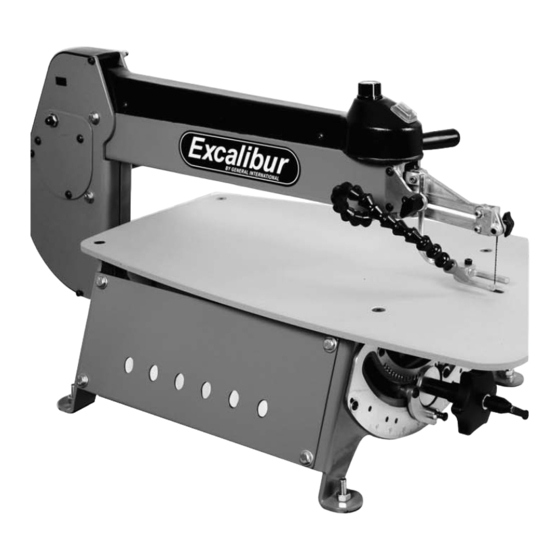
21” SCROLL SAW EX-21 IDENTIFICATION OF MAIN PARTS AND COMPONENTS SIDE VIEW VARIABLE BLADE SPEED CONTROL KNOB TILT HANDLE ON/OFF SWITCH ANGLE INDICATOR BLADE TENSION LEVER ANGLE ADJUSTMENT SCALE BLADE CLAMP MOUNTING HOLES (4) BLADE BLOWER WORKPIECE HOLD DOWN UPPER ARM TABLE MOTOR BLADE TILT LOCKING LEVER... -
Page 8: List Of Contents
UNPACKING & SET UP UNPACKING Carefully unpack and remove the scroll saw and its components from the box and check for missing or damaged items as per the list of contents below. Note: Please report any damaged or missing items to your General International distributor immediately. LIST OF CONTENTS Once the parts have been removed from the packaging, you should have the following items:... - Page 9 Attaching the leveling feet Installing the optional stand Install the leveling feet as shown. Loosen the upper If you prefer an optional stand (item EX-21BS is avail- able from your local General International dealer. and lower nuts as needed to adjust the height The stand is equipped with mounting holes allowing of the foot.
- Page 10 CHOOSING & INSTALLING A SAW BLADE Blade Selection Blade selection is dependent on the type and thickness of the material being cut, but is also a matter of experience and personal preference. There are numerous types of blades available on the market specifically suited for vari- ous cutting applications such as metal-cutting and spiral blades which cut in all directions.
-
Page 11: Operating Instructions
Installing or changing blades Fig. 1 Always turn off and unplug the machine before removing, han- dling or changing blades. Remove an installed, worn or broken blade by loosening the thumb- screws on the upper and lower blade mounts until the blade can be removed. - Page 12 Blade speed selection is subjective and is dependant on a variety of factors: type and thickness of material being cut, type of blade being used, feed rate, required finish quality as well as experience, personal preference and com- fort level of the user. There are no hard and fast rules. Be patient – practice and experience will be your best teacher. Here are some general guidelines to consider when selecting/adjusting blade speed: •...
- Page 13 With the saw turned off and unplugged, install the appropriate blade for Straight Cuts Fig. 7 the type of material to be cut and the type of cut to be made (Refer to the section “Choosing and Installing a Saw Blade” on page 9). Adjust the workpiece hold-down and the blower nozzle to your liking.
- Page 14 Release tension on the blade by pushing the blade tension lever towards the rear of the saw. Loosen the thumbscrew on the lower blade mount, located under the table, to release the blade from the mount. Raise the upper arm assembly which will lift the blade up through the hole and above the table. Position the workpiece on the table so that the guide hole lines up with the hole in the table.
- Page 15 MAINTENANCE, ADJUSTMENTS AND SERVICING Handling Never lift the saw by the upper arm assembly as this Rather lift the saw by the front of the table and by will result in damage to the drivetrain. the motor. Maintenance • Always release tension on the blade when the saw is not in use.
- Page 16 NOTES...
- Page 18 PARTS LIST - EX-21 (A) PART N0. DESCRIPTION SPECIFICATION EX21-A01 MAIN BODY EX21-A02 UPPER ARM EX21-A03 TOP COVER EX21-A04 ALLEN SCREW #10-32X1/4 EX21-A05 SWITCH COVER EX21-A06 SWITCH EX21-A07 SCREW 5/16-5/8 EX21-A08 PLASTIC WASHER EX21-A09 SPRING PIN 1/4X5/8 EX21-A10 TENSION LEVER ASS’Y EX21-A11 TENSION LEVER HANDLE EX21-A12...
- Page 20 PARTS LIST - EX-21 (B) PART N0. DESCRIPTION SPECIFICATION EX21-B01 TRUNNION EX21-B02 SIDE PANEL EX21-B03 REAR TRUNNION PLATE EX21-B04 FRONT TRUNNION PLATE EX21-B05 TABLE EX21-B06 GROUND JUMPER EX21-B07 POWER CORD EX21-B08 SPONGE BLOCK EX21-B09 POLYFOAM EX21-B10 SCREW 1/4-20UNC X1/2 EX21-B11 LOCK WASHER EX21-B12 WASHER...
- Page 22 PARTS LIST - EX-21 (C) PART N0. DESCRIPTION SPECIFICATION EX21-C01 MOTOR EX21-C02 BALANCE BLOCK EX21-C03 SET SCREW M6 X 6 EX21-C04 ALLEN SCREW 1/4-20X1/2 EX21-C05 LOCK WASHER EX21-C06 FLAT WASHER 1/4X16X1.8 EX21-C07 MOTOR COVER PLATE EX21-C08 SCREW M6X16 EX21-C09 BEARING 608ZZ EX21-C10 MOTOR CAM...
- Page 23 EX-21 8360, Champ-d’Eau, Montreal (Quebec) Canada H1P 1Y3 Tel.: (514) 326-1161 Fax : (514) 326-5565 Parts & Service Fax : (514) 326-5555 Order Desk orderdesk@general.ca www.general.ca IMPORTANT: When ordering replacement parts, always give the model number, serial number of the machine and part number. Also a brief description of each item and quantity desired.
Need help?
Do you have a question about the CTEX-21CE and is the answer not in the manual?
Questions and answers