
Summary of Contents for Jenny Reciprocating Air Compressors
- Page 1 ¤ ¤ Reciprocating ¤ Compressors Operation and Maintenance Manual Jenny Products, Inc. 850 North Pleasant Avenue Somerset, PA 15501-1069 Ph:814-445-3400 ● Fx:814-445-2280 www.jennycompressor.com ● info@jennycompressor.com...
-
Page 2: Table Of Contents
Table of Contents Section 1 Preparation for Use..........Safety and Health Instructions Lubrication............Air Cleaner............Adjusting Regulator..........Safety and Health Instruction for Safe Use....Connecting and Disconnecting Hoses....Draining Air Receiver Condensate....... Section 2 Humid Areas............Introduction and Description Dual Voltage Switch..........Noise Considerations.......... - Page 3 You will f nd this booklet a valuable guide to the proper and safe operation and maintenance of your new Jenny. It is intended to be used by anyone using or maintaining the equipment. Follow the instructions carefully and you will assure yourself of the utmost in compressed air eff ciency and...
-
Page 4: Safety And Health Instructions
Section 1 Safety and Health Instructions... -
Page 5: Safety And Health Instruction For Safe Use
I m p o r t a n t ! SAFETY AND HEALTH INSTRUCTIONS FOR SAFE USE THIS PRODUCT CAN CAUSE SERIOUS INJURY OR DEATH IF NOT USED IN ACCORDANCE WITH THE FOLLOWING SAFETY INSTRUCTIONS. WE CAN NOT ANTICIPATE EVERY POSSIBLE CIRCUMSTANCE THAT MIGHT INVOLVE A POTENTIAL HAZARD. - Page 6 Do not replace a fuse or circuit breaker with one of a higher rating without being certain the wire size is adequate to handle the increased electrical load. Keep all electrical connections dry and off of the ground. Observe all local and national codes for the installation and use of this type of equipment. Please use the following criteria for wire selection.
- Page 7 6. Do not operate this unit with any components rated less than the maximum operating pressure of the unit. This unit was designed to compress air at a specif c operating pressure and volume. Never exceed the pressure rating of air tools, spray guns, air operated accessories, tires, and other inf atables.
- Page 8 10. Never modify or alter this unit. For your own safety as well as others, never allow this unit to be altered or modif ed. Modifying or altering equipment to operate in a fashion other than its original design may cause serious injury or death.
- Page 9 15. Do not operate near f ammable or combustible materials. This product is not intended for use in locations where f re or explosion hazards may exist due to the presence of f ammable vapors, liquids or gases, or combustible dusts or f bers.
- Page 10 Safety Data Sheet (MSDS) for the material being used. Use a NIOSH/MSHA approved respirator designed for use each specif c application. Always wear the appropriate approved safety equipment. Always operate the compressor in a well ventilated area. Always store f ammable materials in a secure location away from all open f ames, sparks, and heat sources.
- Page 11 22. Do not permit untrained personnel to maintain or make repairs on this unit. Only qualif ed personnel should be permitted to make any type of repairs to this unit. Improper repairs may cause this unit to malfunction which could result in serious injury or death to the operator, repair person, or bystander.
- Page 12 30. Always release the system pressure prior to service, storage, daily shutdown, and/or disconnecting the hose or from the unit. Always release pressure prior to service, storage, daily shutdown, and/or disconnecting the hose from the unit. Pressure contained within the unit could be released unexpectedly and could cause injury.
- Page 13 Ground the lead to prevent sparks that could cause f res. 40. Use only Jenny repair parts and accessories. To preserve the safety features that are built in to this product, use only Jenny repair parts and accessories.
-
Page 14: Introduction And Description
Section 2 Introduction Description... -
Page 15: Introduction
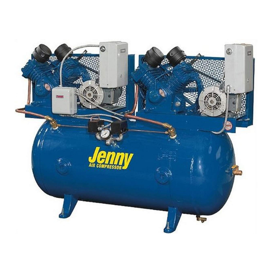
Manufactured by Jenny Products, Inc., 850 North Pleasant Avenue, Somerset, PA 15501 GENERAL DESCRIPTION The Jenny Air Compressor is a reciprocating piston oil bath crankcase air compressor driven by either an electric motor or gasoline engine mounted either on a base or air compressor receiver. -
Page 16: Single Stage And Two Stage Reciprocating Pumps
or gasoline engine V-belt drive sheave assembly. The pumping unit is either a Single Stage or Two Stage Reciprocating Pump. SINGLE STAGE AND TWO STAGE RECIPROCATING PUMPS Reciprocating (Piston) Compressors can be widely found in these two primary conf gurations; Single Stage and Two Stage. -
Page 17: Start-Stop Control Units
valve directs the f ow into the air system or to the atmosphere. Start-Stop Control Units As with constant run units, the air intake is controlled by air pressure demand. Instead of being controlled by a pilot valve, Start-Stop units are controllled by an electrical switching device, called a pressure switch. -
Page 18: Pressure Regulator
motor. Once the air demand drops the system pressure to a predetermined set point, the pressure switch activates and closes the switch and subsequently starts the electric motor. Many pressure switches also contain a special unloading device which relieves the pressure from the compressor pump when the motor is shut off. -
Page 19: Section
Section 3 Preparation for Use Initial Installation Instructions... -
Page 20: General
PREPARATION FOR USE GENERAL The Jenny Air Compressor unit was thoroughly tested at our factory as part of the manufacturing process. The machine will function as designed if properly assembled, set up, and operated. There are certain steps that must be taken prior to attempting to operate unit to assure it is ready for operation. -
Page 21: Servicing Of New Equipment
This information is a guideline for a typical shop installation and is not all inclusive. If there are questions concerning the installation, please do not hesitate to contact your Jenny representative or the Jenny Compressor Company if additional information is required. - Page 22 This unit requires adequate ventilation and must be placed in a location which provides at least three feet of clearance to all adjacent construction. Failure to allow adequate ventilation or CAUTION restrict the air f ow may cause the machine to overheat. Damage to the machine, operator, and any other unit, product, and accessory in the air stream may result.
- Page 23 4.) Ensure the new equipment service was performed prior to operation. 5.) Review all Danger, Warning, and Caution information located on the machine and in the Operator’s Manual. 6.) Check to be certain that all the control switches are in the off position. WARNING The unit is capable of starting automatically.
-
Page 24: Operating Instructions
Section 4 Operating Instructions... -
Page 25: Operating Controls And Indicators
OPERATING CONTROLS AND INDICATORS Jenny compressors are designed to be highly reliable and very simple to operate. Therefore, there are only a few operating control and indicators. They are as follows: On/Off Switch (SW-3, SW-4, Start/Stop Control & Dual Control)- A switch which allows the operator to manually turn the machine on and off. -
Page 26: Dual Voltage Switch
PREPARATION FOR USE Read and understand the safety instructions before using any Jenny Air Compressor. Prior to any use of the compressor, it is important to follow the check list outlined below: 1.) Check the pump and gasoline engine (if so equipped) to ensure proper oil levels as... -
Page 27: Air Cleaner
AIR CLEANER The air cleaner is of the dry, replaceable type. One of the most important service requirements for long term maintenance free operation is to replace or clean the air cleaner element regularly. Excessive wear, high oil consumption and poor performance will result if the air cleaner is clogged or allows contamination to enter CAUTION the compressor. -
Page 28: Draining Air Receiver Condensate
Never decouple the quick coupler when the machine is running. WARNING Always release the pressure in the system before coupling or decoupling. DRAINING AIR RECEIVER CONDENSATE 1. Ensure that the ON/OFF switch is in the OFF position or disconnect the power from the power source. -
Page 29: Noise Considerations
3. Replace the safety hitch pin in the guard. 4. Check and/or replace the plug with the UL/CSA listed plug for the rated current and voltage. Follow the cord plug manufacturers installation instructions and procedures or contact a qualif ed electrician. -
Page 30: Transporting
TRANSPORTING (Portable Compressors) If the unit is a portable type either hand carry or wheeled portable, care must be taken when transporting the compressor. When transporting the compressor in a vehicle, trailer, etc. ensure that the tanks are drained and the unit is secured and placed on a f at horizontal surface. Secure the machine in place by use of a rope or some type of strapping. -
Page 31: Condensate Discharge Piping
CONDENSATE DISCHARGE PIPING If installing a condensate discharge line, the piping must be at least one size larger than the connection, as short and direct as possible, secured tightly and routed to a suitable drain point. Condensate must be disposed of in accordance with local, state and federal laws and regulations. REFUELING (If gasoline engine equipped) The fuel tank is located on top of the gasoline engine or in an approved red gasoline container. -
Page 32: Starting Procedure
not connect the equipment-grounding conductor to a live terminal. Check with a qualif ed electrician or service personnel if the grounding instructions are not completely understood or if in doubt as to whether the unit is properly grounded. Use only 3-wire extension cords that have 3-prong grounding CAUTION plugs and 3-pole receptacles. - Page 33 Do not operate this unit with any components rated less than the CAUTION maximum operating pressure of the unit. 9.) If machine is electric powered, connect electrical service using a fusible disconnect switch. Ensure that the machine is connected to the proper power supply both amperage and voltage. Ensure that all connections are properly tightened.
-
Page 34: Shutdown Procedure
Start/Stop Control - If the unit is Start/Stop equipped and does not have an On/Off switch turn the OFF-AUTO (MAN) switch from the OFF position to either the MAN or AUTO position. If the unit is equipped with an On/ Off switch move the switch to the On position. - Page 35 switch from either the MAN or AUTO position to the OFF position. If the unit is equipped with an On/ Off switch move the switch to the OFF position. Stopping Gasoline Engine (If so equipped) - If so equipped, your air compressor is powered by a gasoline engine. Most accidents with engines can be prevented if you follow all instructions in this manual, the engine owner’s manual and on the engine.
- Page 36 Section 5 Maintenance Instructions...
-
Page 37: Preventive Maintenance
9. Fill the crankcase with Jenny Ultimate Blue synthetic oil. Oil should not exceed top raised line on side of crankcase (oil will be even with bottom of threads in crankcase f ll port). -
Page 38: Checking Safety Relief Valve Operation
CHECKING SAFETY RELIEF VALVE OPERATION Aftercooler, pump head, and surrounding parts are very hot, do WARNING not touch. 1. Ensure unit is off and disconnected from the power source. 2. Ensure tanks are empty by looking at tank pressure gauge. Drain tanks if necessary. 3. -
Page 39: Pilot Valve Pressure Differential Adjustment
2. Turn screw “A” clockwise to increase cut-out pressure limit or counter clockwise to decrease cut- out pressure. (example: if the cut-out pressure on the tank gauge reads 120 psi. and desired cut out is 130 psi, turn screw “A” clockwise) 3. -
Page 40: Drive Belt Adjustment
There is live electrical power on the four contact points on the switch. Use only electrically insulated tools to perform this adjustment in case of accidental contact with the electrical system. Pressure Range Adjustment To increase the pressure range: Turn screw A clockwise to increase the overall system pressure range (both cut-in and cut-out). -
Page 41: Checking For Air Leaks
reference location. 9.) If the def ection of belt too great, then loosen the motor or engine bolts and slide the motor or engine away from the pump. If the def ection of belt too small, then loosen the motor or engine bolts and slide the motor or engine toward the pump. -
Page 42: Preventive Maintenance Schedule
To ensure eff cient maintenance free life span, the Jenny compressor must be serviced and maintained by the operator and qualif ed maintenance personnel on a periodic and systematic basis. -
Page 43: Service Information
For the closest warranty repair center, please contact us. WARRANTY Full One Year Warranty - Jenny Compressors are warranted for one year from date of purchase. We will repair, without charge, any defects due to faulty materials or workmanship. -
Page 44: Troubleshooting
Section 6 Troubleshooting Instructions... - Page 45 In some cases, the operator or maintenance personnel can perform the corrective actions, while others may require the assistance of a qualif ed Jenny compressor technician or dealer. This procedure has been written assuming that the unit has been installed correctly, has been operating and functioning correctly.
- Page 46 Unit does not or is slow to come up Lubricant viscosity too high. Drain existing lubricant and ref ll to speed. with Jenny Ultimate Blue Synthetic lubricant. Carbon build up on top of piston. Clean piston. Repair or replace as required.
- Page 47 Check joint with soap solution. Do not overtighten. Crankcase overf lled with oil. Drain oil. Ref ll to proper level with Jenny Ultimate Blue Synthetic Oil. Manual lock on pilot valve is in the Move manual lock into an in-line loaded position.
- Page 48 Clogged or dirty inlet and or Clean or replace. accessory discharge line f lter. Lubricant viscosity too high Drain existing lubricant and ref ll with Jenny Ultimate Blue Synthetic lubricant. Compressor check valve leaky, Clean or replace as required. broken, carbonized or loose. Inspect valves.
- Page 49 (reed) valve. Clear or replace valves as required. High oil consumption. Lubricant viscosity too low Drain existing lubricant and ref ll with Jenny Ultimate Blue Synthetic lubricant. Extremely light duty cycles. Run unit for longer duty cycles Piston rings damaged or worn Install new rings.
- Page 50 Excessive noise during operation Lubricant viscosity too low Drain existing lubricant and ref ll with Jenny Ultimate Blue Synthetic lubricant. Lubricant viscosity too high. Drain existing lubricant and ref ll with Jenny Ultimate Blue Synthetic lubricant.
- Page 51 10° in any direction while running. Crankcase overf lled with oil. Drain oil. Ref ll to proper level with Jenny Ultimate Blue Synthetic Oil. Moisture in discharge air. Condensation in air tank caused by Drain air tank after every use.
- Page 52 Air tank must be replaced. Do not attempt to repair air tank Water in oil due to condensation. Drain oil. Ref ll to proper level with Jenny Ultimate Blue Synthetic Oil. Unit located in damp or humid Relocate unit. location.
- Page 53 Abnormal piston ring or cylinder Lubricant viscosity too low Drain existing lubricant and ref ll wear. with Jenny Ultimate Blue Synthetic lubricant. Lubricant level too low Add Jenny Ultimate Blue Synthetic Oil to crankcase to proper level.
Need help?
Do you have a question about the Reciprocating Air Compressors and is the answer not in the manual?
Questions and answers