
Subscribe to Our Youtube Channel
Related Manuals for BW Broadcast DSPX-FM


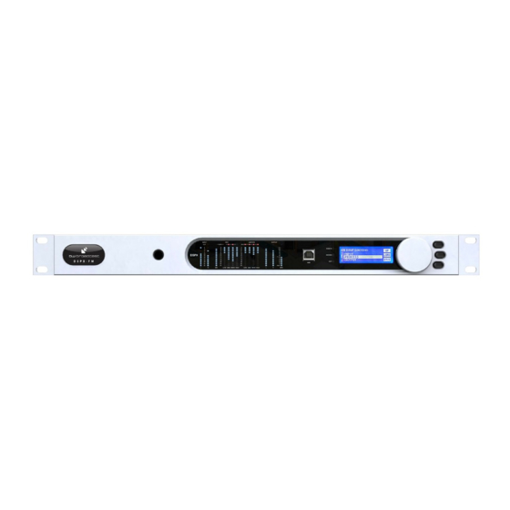
Summary of Contents for BW Broadcast DSPX-FM
- Page 1 DSPX-FM Broadcast Audio Processor Operational Manual Version 3.20 www.bwbroadcast.com...
-
Page 2: Table Of Contents
Table Of Contents Warranty Safety Forward Introduction to the DSPX DSPX connections DSPX meters Status LEDS Quickstart An introduction to audio processing Source material quality Pre-emphasis The DSPX and its processing structure The processing path Processing block diagram The DSPX menu system The Menu stucture Setting up the processing on the DSPX Getting the sound that you want... -
Page 3: Warranty
If the product shows any defects within the specified warranty period that are not due to normal wear and tear and/or improper handling by the user, BW Broadcast shall, at its sole discretion, either repair or replace the product. If the unit has a manufacturers fault within twenty eight (28) days then BW Broadcast will pay the freight at their discretion. -
Page 4: Safety
The appliance should be cleaned only as recommended by the manufacturer. Non-use Periods: The power cord of the appliance should be unplugged from the outlet when left unused for a long period of time. Page 4 BW Broadcast Technical Manual... - Page 5 Radio Interference Regulations of the Canadian Department of Communications. Le present appareil numerique n'emet pas de bruits radioelectriques depassant les limits applicables aux brouillage radioelectrique edicte par le ministere des Communications de Canada. Page 5 BW Broadcast Technical Manual...
-
Page 6: Forward
X represents many things. DSPX was born. Once again, thank you for your purchase; we hope you enjoy the DSPX! BW Broadcast Team Forward... -
Page 7: Introduction To The Dspx
dSPX NTROdUCTION The BW DSPX is a new generation of digital audio signal processor that can be used to process audio ready for FM and digital broadcast. The DSPX is the first UK designed and manufactured multi-band digital broadcast processor. Using the latest multi-band DSP technology the DSPX offers a versatile and powerful tool in creating a loud punchy on-air pres- ence. -
Page 8: Dspx Connections
Connections... -
Page 9: Dspx Meters
dSPX M ETERS The DSPX has 182 LEDS that provide ‘always on’ instant IO and processing metering. INPUT LIMITERS OUTPUT HOLD CLIP GATE CLIP CLIP REMOTE DSP X AES/EBU EDIT PILOT MIDL MIDH HIGH MIDL MIDH HIGH I/O metering The input meters show the level of the input audio. The meters are ‘hooked in’ to the DSP code after the input level selection and mode options. -
Page 10: Quickstart
UICk START 1. Install the processor into the rack. 2. Connect AC power to the unit, and turn on the power. 3. Connect the analogue and / or digital audio inputs. 4. Select the analogue or digital input as the source of the processing with the 'INPUT SELECTION' parameter which can be found in the 'INPUT' menu. -
Page 11: An Introduction To Audio Processing
NTROdUCTION UdIO ROCESSING Most audio processors use a combination of compression, limiting and clipping to 'funnel' the dynamic range down, reducing the peak to average ratio in each stage. A cascaded arrangement of compressor, limiter and clipper produces the best results. The first stage of processing usually operates in a slow manner, the process- ing getting progressively faster and more aggressive as the audio passes through the chain. -
Page 12: Source Material Quality
DSPX processing. EMPhASIS If you are using the DSPX-FM to process for FM broadcast you will need to enable the pre-emphasis filter in the DSPX. Even though your STL or transmitter may contain pre-emphasis we recommend disabling it, letting the DSPX- FM handle the pre-emphasis for the transmission system. -
Page 13: The Dspx And Its Processing Structure
dSPX A ROCESSING TRUCTURE The DSPX broadcast audio processor can be used for processing audio prior to broadcast on FM and digital radio services. Digital radio encompasses DAB,HD,IBOC and other radio based broadcasting as well as internet radio, known also as streaming. The DSPX can also be used effectively for audio post production and mastering, ideal for giving CD’s that HOT sound. - Page 14 couplings and complex gating features afford the user with full control of this important re-equalisation stage of the processor. Multi-band Limiters Each band has its own dynamic peak limiter. Multiple time constant based detectors with built in adjustable hold and delay functions significantly reduce distortion. Mixer The four bands are 'virtually' mixed together at this stage.
-
Page 15: Processing Block Diagram
Processing Block diagram... -
Page 16: The Dspx Menu System
YSTEM vERvIEw This section presents an overview of the four main menus and thier submenus and any parameters that are con- tained in them. INPUT: Contains all the controls that affect input selection, level control and signal conditioning. PROCESS: Contains all the controls that affect the processing. OUTPUT: Contains all the controls that affect output selection, level control and signal conditioning. -
Page 17: The Menu Stucture
COMPOSITE CLIPPER TRUCTURE ADVANCED: DYNAMIC MB CLIPPING MENU: INPUT MAIN CLIP FINESSE SOURCE OVERSHOOT CONTROL STEREO MODE MAIN CLIP TYPE ANALOG INPUT LEVEL ITU LIMITER RIGHT TRIM INPUT FAIL SWITCH MENU: OUTPUT HIGH PASS FILTER MENU: ANALOG PHASE ROTATOR MODE PRE-EMPHASIS OUTPUT LEVEL DE-EMPHASIS... - Page 18 ROCESSING ARAMETERS The 'INPUT' menu contains all of the options and parameters relating to the control and conditioning of the audio inputs. 'SOURCE' This parameter allows you to select the between the analog and digital inputs as the source for the processing.
- Page 19 'GATE THRESHOLD' The gate function prevents 'suck-up' of noise during periods of silence or low level audio. The level can be adjusted to turn on when the input drops to a level from -20dB to -40dB. The gate can also be switched off or forced on. The gate when turned on will cause the gain reduction to move towards the level set by the RTR LEVEL control and to move towards that level at the rate set by the RTR speed control.
- Page 20 'ATTACK' Controls the attack rate of the AGC, The time the AGC takes to respond to an increase of input level. The attack time can be varied between 1 and 10 which corresponds to 100mS to 30S on a semi-exponential scale. 'DECAY' Controls the release/decay rate of the AGC, the time the AGC takes to respond to a decrease of input level.
- Page 21 The 'MULTI-BAND LIMITERS' peak limit each of the bands to prevent distortion in the processors clipping peak control system. 'B1-4' 'DRIVE' Controls the drive into the limiter. The drive can be increased or decreased by up to 12dB. 'THRESHOLD' Sets the limiter threshold. If audio is below threshold, there will be no gain reduction. Audio signals that go above will be attenuated.
- Page 22 'MIXER' menu. Each band can be adjusted over a small range to provide small EQ changes. These controls are limited in range to prevent excessive drive into the peak clipping stages and excess distortion being introduced. A solo mode is provided to aid in the setting up of parameters. BAND1MIX: -3dB to +3dB of level adjustment is available.
- Page 23 the main clippers output level. 'HF CLIP LEVEL' Controls the clip level of band 4. The clip level range is -12dB to 0 dB referenced to the main clippers output level. 'HF CLIPPING' This control redistributes band 4 peak control between the band 4 limiter and the HF clip- per.
- Page 24 'MODE' This parameter sets the output mode of the digital output. The available options are FM and DR representing the distortion controlled clipping path and the lookahead limiting path respectively 'SAMPLE RATE' This parameter sets the output sampling rate for the AES/EBU digital output. The avail- able rates are 32 KHz, 44.1 KHz, 48 KHz, follow digital input rate and follow external sync rate.
- Page 25 'OUTPUT LOCK' This enables or disables the output code lock. The options are enabled and disabled. More information is available in the code lock section of this manual. 'REMOTE SOURCE' This selects the serial port or the NET/LAN port as the remote control method. The default option is Off.
-
Page 26: Setting Up The Processing On The Dspx
dSPX ETTING UP ThE ROCESSING ON ThE This section has more detailed information on setting up the DSPX’s processing. The section is laid out in the same order as the processing route through the DSPX. High pass filter The high-pass filter has five selectable cut off frequencies and a bypass option. Most users will bypass the high- pass stage but there are several cases where enabling the high-pass has an advantage. - Page 27 The effects of time constant speeds AGC attacking and decaying with faster time AGC attacking and decaying with slower time constants constants this manual as 'forced gating' as it has the effect of switching the gate on at all times with any level of program material.
- Page 28 The last gating option available to the wideband AGC is window gating. Window gating is separate from the silence gating that we have been discussing in that it does not work on the amplitude of the audio, rather the peak to average ratio of the waveform and how the waveform is changing over time. The window gating feature if enabled freezes the gain over a pre-defined range and will only let gain control commence once the waveform has fallen outside of this pre-determined range.
- Page 29 Frequencies selectable: 60Hz, 76Hz, 95Hz and 120Hz. Q's selectable: 0.4, 1, 2 and 4. Gains selectable: 0, 1.5dB, 3dB, 4.5dB, 6dB. A starting setting of 95Hz, Q of 1 and gain of 4.5dB warms the bass up quite nicely but you are free to experiment to get the bass sound you're after.
- Page 30 To force gate a band you need to set the gate threshold control for that band to 'ON'. You then need to adjust the RTR level to set the gain reduction in that band. The gain through the stage will equal ((BAND DRIVE in dB - 12dB) - RTR LEVEL in dB).
- Page 31 balance between peak and average energy in the detector. With smaller numbers more energy is transferred into the average circuit and a higher platform level is created so more time will be spent releasing at the slower average rate. Higher numbers offer slower attack times for the averaging part of the detector and this has theef- fect of lowering the average platform level and allowing the peak part of the circuit to dominate with its faster release times.
- Page 32 Without hold with hold Delay The delay control sets the amount of time the processor will hold the gain reduction for before releasing at the peak decay rate. Careful setting of this control allows us to speed up the peak decay time without introdudc- ing the audible effects of faster decay times.
- Page 33 The mixer The post limiters mixer in the DSPX is not strictly a mixer but a band output level control where small EQ chang- es can be made. It has been called the mixer as most other processors have a mixer at this position and our VIRTUAL mixer does the same job.
- Page 34 level for the bass (mix of bands 1 and 2) and leave the remaining half for the sum mix of the mid-clipper and the HF-clipper. If these two clippers' clip thresholds were set so that they didn't add up to more than 50% modula- tion, say -12dB and -12dB then the main clipper would have no work to do as all of the peak control would be done with the multi-band clippers.
- Page 35 and distortion that your listeners will find uncomfortable to listen to especially for extended periods of time. We also suggest that you make final clipper drive adjustments in tandem with the multi-band clipper drive as what is taken from or added from one can usually be made up for with the other. The final clipper now has an additional control to help reduce IMD distortion.
-
Page 36: Getting The Sound That You Want
may not be immediately obvious. The HF clipping control (located in the band 4 limiter and clippers menus) redistributes control of high frequency energy from the band 4 limiter into the following processing stage. For the FM path this HF energy gets handled by the HF clipper but in the case of the look-ahead limiter this high frequency energy can modulate the rest of the audio waveform and introduce a pumping type sound. - Page 37 ETTING OUNd While the DSPX can help you obtain the sound that you want we must always take into account the limitations presented to us by the transmission channel. The biggest problem we have is the maximum peak level that can be handled by that transmission channel.
- Page 38 ABOVE SUGGESTIONS THEN YOU PROBABLY HAVE A BIT MORE LEE-WAY. IT IS VERY EASY TO LOSE YOUR WAY ONCE YOU START 'CRANKING' LOTS OF DIFFERENT SETTINGS. More CLARITY We can obtain extra clarity and quality in several ways. Multi-band AGC: Slow down the release times, making them slower.
- Page 39 Slow down the peak attack time for band 1, letting more through to the clippers. Speed up the release time of the average release time constant. Slow down the band 1 average attack time so that the peak time constant dominates the control signal pro- viding faster control.
- Page 40 Increase the band 4 look-ahead limiter attack time constant slowing down the attack of the secondary time constant circuit. Decrease the band 4 look-ahead limiter decay time constant speeding up the decay of the secondary time constant circuit. WE SUGGEST ONLY SMALL MODIFICATIONS FROM FACTORY PRESET SETTINGS IF YOU ARE MODYFYING LOTS OF THE PARAMETERS.
-
Page 41: Managing Presets
FRONT PANEL CONTROL The DSPX-FM has an assortment of factory presets and provision for 8 user ones. While the factory presets may not suit your tastes you will generally find one that serves as a good starting point in creating your own custom preset. - Page 42 ACTORY RESETS The factory presets in the DSPX are not supposed to be de-facto standards by any means but are starting points for you to create your own user presets. It is impossible to create presets that will suit every format and market. What is right for one market is not usually right for another.
-
Page 43: Remote Control Of The Dspx
ONTROL In addition to the front panel LCD control system the DSPX-FM has a USB port, a serial port and an ethernet/ LAN port. These allow remote control of the DSPX-FM through a remote application program running on a win- dows based PC. - Page 44 If you wish to use the NET/LAN port to control the DSPX-FM follow the steps below 1. Connect a cat 5 cable to the RJ45 port on the DSPX-FM and plug this into your network hub/switch. A Xover cable can be used to connect directly to a PC if you don’t have a switch or hub.
- Page 45 The DSPX-FM contains two levels of password control, a high level password which blocks access to all areas of the DSPX-FM and an ‘Output’ level password that allows access to all areas of the DSPX-FM except the out- put menus that contain the output mode and level settings. The ‘Output’ level password could be given to pro- gramme controllers to adjust the processing knowing that the transmission will remain compliant as there is no way for the user to adjust the peak output level of the DSPX-FM.
- Page 46 Understanding the preset list The preset list contains all of the presets contained in the DSPX-FM. The user presets are prefixed U1 to U8 and the factory presets from F1 onwards. You may need to use the scroll arrows to view all of them as they won't all fit in the window at one time.
- Page 47 'on air'. The exception to this is when the default preset is being overridden by a daypart or remote trigger. In this case the DSPX-FM will 'on air' the selected preset when the daypart or trigger hands back control to the default preset.
- Page 48 There are three menu locations for controlling scheduling. The first location is shown in the screen shot below and it contains the ON/OFF and time setting control. The two menu locations below it access two banks of four dayparts which make up the 8 dayparts contained in the DSPX-FM. Scheduling On the daypart windows you have four dayparts.
- Page 49 The dayparts can be layered so that one can override another. Let's say the default preset was U1:MAIN PRESET and this was on the air all of the time. We want to change the preset from 7AM to 10AM every day of the week to F2:CHR and then from 10AM to 12PM we want U4:NEW PRESET and then back to F2:CHR until 5PM.
-
Page 50: Remote Trigger Port
MITERS OUTPUT HO LD DSPXtra REMOTE INPUT LOAD PROCESS AES/EBU OUTPUT SAVE EDIT EMOTE RIGGER The system menu contains the remote trigger port option from where it can be enabled or disabled. If enabled the remote trigger port on the processor allows you to select any of the first 8 user presets by pulling one of 8 pins on the trigger port socket low. -
Page 51: Security Code Lock
The system menu contains the security code lock options from where they can be enabled or disabled. The DSPX-FM has two code locks, the main full lock and the output lock. When enabled the full code lock prevents editing of the DSPX-FM parameters. When enabled the output lock restricts access to the output menu section of theDSPX-FM. -
Page 52: Clock Based Control
LOCk ASEd ONTROL AYPARTING Your processor contains a battery backed up real time clock that can maintain the current time and date even when the power has been removed. This allows users to switch between presets at specific times of the day or week. -
Page 53: Specifications
PECIFICATIONS Specifications apply for measurements from analog left/right input to stereo composite output and to FM analog left/right output. Measurements apply to FM mode of operation. Frequency Response (Bypass Mode): Follows standard 50µs or 75µs pre-emphasis curve ±0.10 dB, 2.0 Hz– 15 kHz. - Page 54 MPX output Source Impedance: 10 Ohm Single-ended, floating over chassis ground. Load Impedance: 600 Ohm or greater. Maximum Output Level: +12.0 dBu (peak) software-controlled output level control Minimum Output Level: 0dBu (peak)Software-controlled output level control Pilot Level: Adjustable from 6.0% to 12.0% and OFF, software controlled. Pilot Stability: 19 kHz, ±1 Hz (10 degrees to 40 degrees C).
- Page 55 APPENDIX A Installing USB VCP Drivers To install the VCP drivers for the processor under Windows XP and XP SP1, follow the instructions below: If a device of the same type has been installed on your machine before and the drivers that are about to be installed are different from those installed already, the original drivers need to be uninstalled.
- Page 56 Select “Install from a list or specific location (Advanced)” as shown below and then click “Next”. Select “Search for the best driver in these locations” and enter the file path in the combo-box (“C:\VCP Drivers” in the example below) or browse to it by clicking the browse button. Once the file path has been entered in the box, click next to proceed.
- Page 57 The following screen will be displayed as Windows XP copies the required driver files. Windows should then display a message indicating that the installation was successful. Click “Finish” to complete the installation. This has installed the serial converter. The COM port emulation driver must be installed after this has completed.
- Page 58 The following screen will be displayed as Windows XP copies the required driver files. After clicking “Finish”, the Found New Hardware Wizard will continue by installing the COM port emulation driver. The procedure is the same as that above for installing the serial converter driver.
-
Page 59: Preset Sheet
DSPX-FM v3 preset sheet Preset 1 Preset 2 Preset 3 Preset 4 INPUT SOURCE MODE ANALOG LEVEL INPUT FAIL HP FILTER PHASE ROTATOR PRE-EMPHASIS µs µs µs µs PROCESS WB AGC DRIVE ATTACK DECAY GATE RTP LEVEL RTP SPEED WINDOW GATING... - Page 60 MB LIMITER MASTER DRIVE LIMITERS RATIO B1<2 COUPLING B2>3 COUPLING B3>2 COUPLING B3>4 COUPLING L/R COUPLING BAND 1 DRIVE THRESHOLD PEAK ATTACK PEAK DECAY AVERAGE ATTACK AVERAGE DECAY HOLD DELAY BAND 2 DRIVE THRESHOLD PEAK ATTACK PEAK DECAY AVERAGE ATTACK AVERAGE DECAY HOLD DELAY...
- Page 61 MID DECAY HIGH ATTACK HIGH DECAY OUTPUT STEREO LEVEL PILOT LEVEL PILOT PROTECTION ITU LIMITER 19kHz SYNC Appendix B - Preset Sheet...
- Page 62 www.bwbroadcast.com...
Need help?
Do you have a question about the DSPX-FM and is the answer not in the manual?
Questions and answers