Table of Contents
Advertisement
TUBULAR GAS FIRED DIRECT SPARK PROPELLER UNIT HEATERS
– FOR COMMERCIAL, INDUSTRIAL AND RESIDENTIAL INSTALLATIONS –
ATTENTION: READ THIS MANUAL AND ALL LABELS ATTACHED TO THE UNIT CAREFULLY BEFORE ATTEMPTING
TO INSTALL, OPERATE OR SERVICE THESE UNITS! CHECK UNIT DATA PLATE FOR TYPE OF GAS AND ELECTRICAL
SPECIFICATIONS AND MAKE CERTAIN THAT THESEAGREE WITH THOSE AT THE POINT OF INSTALLATION. RECORD THE
UNIT MODEL AND SERIAL No.(s) IN THE SPACE PROVIDED. RETAIN FOR FUTURE REFERENCE.
Unit No.
Do not store or use gasoline or other fl ammable vapors and liquids in the vicinity of this or
any other appliance.
can cause property damage, injury, or death. Read the installation, operating, and
maintenance instruction thoroughly before installing or servicing this equipment.
instructions to avoid exposure to fuel substances, or substances from incomplete combustion,
which can cause death or serious illness. The state of California has determined that these
substances may cause cancer, birth defects, or other reproductive harm.
Installer Please Note: This equipment has been test fired and inspected. It has been
shipped free from defects from our factory. However, shipment and installation
problems such as loose wires, leaks, or loose fasteners may occur. It is the installer's
responsibility to inspect and correct any problem that may be found.
RECEIVING INSTRUCTIONS
Inspect shipment immediately when
received to determine if any damage has
occurred to the unit during shipment. After
the unit has been uncrated, check for any
visible damage to the unit. If any damage
is found, the consignee should sign the
bill of lading indicating such damage and
immediately fi le claim for damage with the
transportation company.
01/14
INSTALLATION INSTRUCTIONS AND PARTS IDENTIFICATION
FOR YOUR SAFETY
WHAT TO DO IF YOU SMELL GAS
Do not try to light any appliance.
Do not touch any electrical switch; do
not use any phone in your building.
Immediately call your gas supplier
from a neighbor's phone. Follow the
gas supplier's instructions.
If you cannot reach your gas supplier,
call your fi re department.
Improper installation, adjustment, alteration, service, or maintenance
APPROVED FOR USE IN CALIFORNIA
Install, operate, and maintain unit in accordance with the manufacturer's
INSTALLER'S RESPONSIBILITY
Serial No.
FOR YOUR SAFETY
260 NORTH ELM ST., WESTFIELD, MA 01085
TEL: (413) 568-9571
GG-IOM-10
J30-08511
ENERGY
PERFORMANCE
CM
VERIFIED
RENDEMENT
ENERGETIQUE
VERIFIE
FAX: (413) 562-8437
www.mestek.com
Advertisement
Table of Contents

Subscribe to Our Youtube Channel
Related Manuals for Mestek Tubular 30

Summary of Contents for Mestek Tubular 30
- Page 1 If any damage 260 NORTH ELM ST., WESTFIELD, MA 01085 is found, the consignee should sign the TEL: (413) 568-9571 FAX: (413) 562-8437 bill of lading indicating such damage and www.mestek.com immediately fi le claim for damage with the transportation company. 01/14...
-
Page 2: Table Of Contents
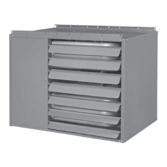
Tubular Unit Heaters are design certified under ANSI have any questions after reading this manual, contact the manufacturer. Figure 1 - Tubular 30 thru 120 Propeller Unit Heaters 120 MBH 30 MBH See Identifi cation of Parts, Figures 22 through 28. -
Page 3: General Safety Information
GENERAL SAFETY INFORMATION Failure to comply with the general Make certain that the power source conforms to the safety information may result in extensive electrical requirements of the heater. property damage, severe personal injury, or death. Do not depend upon a thermostat or other switch as sole means of disconnecting power when installing or servicing heater. - Page 4 Table 1 - Performance and Dimensional Data - Tubular 30 thru 120 Propeller Unit Heater Unit Size PERFORMANCE DATA† Input - BTU/Hr. 30,000 45,000 60,000 75,000 90,000 105,000 120,000 (kW) (8.8) (13.2) (17.6) (22.0) (26.4) (30.8) (35.2) Output - BTU/Hr.
- Page 5 Figure 2 - Dimensional Drawing – Tubular 30 thru 120 Propeller Unit Heater D8597 DIMENSIONS .XXX STANDARD UNITS DIMENSIONS IN PARENTHESIS (XXX) MILLIMETERS...
- Page 6 INSTALLATION Do not install unit heaters in AIR FOR COMBUSTION: The unit heater shall be corrosive or fl ammable atmospheres! Premature installed in a location in which the facilities for ventilation failure of, or severe damage to the unit will permit satisfactory combustion of gas, proper venting, result! and the maintenance of ambient air at safe limits...
-
Page 7: Installation Codes
INSTALLATION (continued) The Unit Heater may be mounted by Figure 3 - Hanger Bracket Installation Instructions fastening the hanging brackets directly to ceiling joists or by suspending from four rods. See Figures 3, 4 and 5. Make certain that the lifting methods used to lift the heater and the method of suspen- sion used in the fi... -
Page 8: Gas Supply Piping
GAS PIPING To avoid damage or possible personal injury, do not connect gas piping to this unit until a supply line pressure/leak test has been completed. Connecting the unit before completing the pressure/leak test may damage the unit gas valve and result in a fi re hazard. Do not rely on a shut-off valve to isolate the unit while conducting gas pressure/leak tests. - Page 9 PIPE INSTALLATION 1. Install the gas piping in accordance with applicable Do not over tighten the inlet gas local codes. piping into the valve. This may cause stresses that 2. Check gas supply pressure. Each unit heater must will crack the valve! be connected to a gas supply capable of supplying its full rated capacity as specifi...
-
Page 10: Electrical Connections
ELECTRICAL CONNECTIONS THERMOSTAT WIRING AND LOCATION: NOTICE: The thermostat must be mounted on a HAZARDOUS VOLTAGE! vertical, vibration-free surface, free from air currents, DISCONNECT ALL ELECTRIC and in accordance with the furnished instructions. POWER INCLUDING REMOTE DISCONNECTS BEFORE Mount the thermostat approximately 5 feet (1.5m) above SERVICING. - Page 11 ELECTRICAL CONNECTIONS (continued) Figure 10A - UT Control Board D8604 Figure 11A - Honeywell Control Board D8605...
- Page 12 ELECTRICAL CONNECTIONS (continued) Figure 10B - Tubular Propeller Units 30-120 with Natural and Propane (LP) Gas with Single Stage Gas Control and UT Control Board NOTICE: See Figures 7, 8, 9, 10B, 10C, 11B and 11C for connecting the thermostat to the unit heater.
- Page 13 ELECTRICAL CONNECTIONS (continued) Figure 10C - Tubular Propeller Units 60-120 with Natural and Propane (LP) Gas with Optional Two Stage Gas Control and UT Control Board NOTICE: See Figures 7, 8, 9, 10B, 10C, 11B and 11C for connecting the thermostat to the unit heater.
- Page 14 ELECTRICAL CONNECTIONS (continued) Figure 11B - Tubular Propeller Units 30-120 with Natural and Propane (LP) Gas with Single Stage Gas Control and Honeywell Control Board NOTICE: See Figures 7, 8, 9, 10B, 10C, 11B and 11C for connecting the thermostat to the unit heater.
- Page 15 ELECTRICAL CONNECTIONS (continued) Figure 11C - Tubular Propeller Units 60-120 with Natural and Propane (LP) Gas with Optional Two Stage Gas Control and Honeywell Control Board NOTICE: See Figures 7, 8, 9, 10B, 10C, 11B and 11C for connecting the thermostat to the unit heater.
- Page 16 VENTING* All unit heaters must be vented! All Venting installations shall be in accordance with the latest edition of Part 7, Venting of Equipment of the National Fuel Gas Code, ANSI Z223.1 (NFPA 54), or applicable provisions of local building codes. All venting of residential tubular unit heaters must comply with CSA International Requirements 10.96 U.S.
-
Page 17: Venting General
VENTING - GENERAL GUIDELINES The following guidelines apply to all categories to follow. Vent connectors serving Category I and Category II heaters shall not be connected into any portion of Table 4 mechanical draft systems operating under positive vent pressure. Vent Systems Termination Clearance Requirements Maintain clearance between the vent pipe and combustible... -
Page 18: Standard Combustion
STANDARD COMBUSTION VERTICALLY VENTED, CATEGORY I - Figure 12 Observe the following precautions when venting the unit: 3. Slope horizontal runs upward from the gas unit heater 1. Use fl ue pipe of the same size as the fl ue connection(s) at least 1/4-inch per foot (21mm/m) minimum. - Page 19 Figure 12 - Vertically Vented, Category I D9257 Figure 12A - Double Wall Draft Hood Connector D06880...
- Page 20 STANDARD COMBUSTION HORIZONTALLY VENTED, CATEGORY III - Figures 13A, 14 & 16 Observe the following precautions when venting the unit: 7. Maintain clearance between the vent pipe and 1. Use flue pipe of the same size as the flue combustible materials according to vent pipe connection(s) on the gas unit heater, 4 inches manufacturer’s instructions.
- Page 21 Figure 13A - Category III Horizontal Venting Requirements Using Single Wall Vent Pipe D9259 Figure 13B - Vertically Vented, Category III D9258...
- Page 22 VENTING (continued) Figure 14 D9260 Figure 15 D9261...
- Page 23 VENTING (continued) Figure 16 D9262 Figure 17 D9263...
-
Page 24: Separated Combustion
SEPARATED COMBUSTION INSTALLATION - VENTING – CATEGORY III NOTICE: Every Separated Combustion unit to be installed MUST use the Factory available Combustion Air Inlet Kit. If you do not have this kit, contact the manufacturer ASAP to obtain one prior to installation. COMBUSTION AIR 7. - Page 25 SEPARATED COMBUSTION VENTING (continued) 7. The equivalent length of the vent system must not be 4. Use UL 1738 listed single wall pipe for the vent system. For installations in Canada, use corrosion resistant less than 5 feet (1.5m) and must not exceed 30 feet and gas-tight, listed vent pipe conforming with local (9m).
- Page 26 Figure 19 - Vertical Intake/Vent Installation D9264 Figure 20 - Horizontal Intake/Vent Installation D9265 Figure 21 - Horizontal Intake/Vent Installation D9266...
-
Page 27: Venting
SEPARATED COMBUSTION VENTING (continued) NOTICE: Every Separated Combustion unit to be installed MUST use the Factory available Combustion Air Inlet Kit. See installation instructions included with kit for complete list of instructions. If you do not have this kit, contact the manufacturer ASAP to obtain one prior to installation. AIR INLET COLLAR HORIZONTAL TERMINATION Remove screen and mounting plate from air inlet on... -
Page 28: Operation
OPERATION POWER VENTED PROPELLER UNITS DIRECT SPARK IGNITION EXPLANATION OF CONTROLS: 8. The wall thermostat, supplied optionally, is a 1. Each Unit Heater comes equipped with a power temperature sensitive switch that operates the vent system that consists of a power venter motor vent system and ignition system to control the and blower, pressure switch, and sealed flue temperature of the space being heated. -
Page 29: Gas Input Rate
PRIMARY AIR ADJUSTMENT Primary air adjustment is made at the factory. No fi eld adjustments are necessary. GAS INPUT RATE Check the gas input rate as follows (Refer to General inches W.C. (2.5 kPa) must be maintained for proper Safety Information section for metric conversions). operation of the unit heater. -
Page 30: Maintenance
Table 7 High Altitude Deration - United States Manifold Pressure Altitude BTU Output Natural Gas Liquid Propane Feet Meters Inches WC Inches WC Percentage 0-2,000 0-610 2,491 100% 2,001-3,000 611-915 2,292 3,001-4,000 916-1,220 2,092 4,001-5,000 1,221-1,525 1,918 5,001-6,000 1,526-1,830 1,744 6,001-7,000 1,831-2,135 1,594... -
Page 31: Troubleshooting Guide
Table 8 - Tubular Propeller Troubleshooting Guide SYMPTOMS POSSIBLE CAUSE(S) CORRECTIVE ACTION A. Flame pops back. 1. Burner orifi ce incorrect. 1. Check for proper orifi ce size. Refer to “Operation”. 2. Low manifold Pressure. 2. Test and reset manifold pressure. B. - Page 32 Table 8 - Tubular Propeller Troubleshooting Guide (continued) SYMPTOMS POSSIBLE CAUSE(S) CORRECTIVE ACTION I. Burner will not shut off. 1. Thermostat located incorrectly. 1. Relocate thermostat away from outside wall or drafts. 2. Improper thermostat wiring. 2. Check thermostat circuit for open and close on terminal strip on heater “R”...
- Page 33 Table 8 - Tubular Propeller Troubleshooting Guide SYMPTOMS POSSIBLE CAUSE(S) CORRECTIVE ACTION R. Cold air is delivered during 1. Incorrect manifold pressure or input. 1. Refer to “Operation”. heater operation. S. High limit tripping. 1. Unit is over fi red. 1.
- Page 34 Table 9A - Troubleshooting with LED Indicator Assistance for UT Control Board LED STATUS INDICATES CHECK/REPAIR Slow Flash Control OK, no call for heat. Not Applicable Line voltage power can cause product damage, Fast Flash Control OK, call for heat present. Not Applicable severe injury or death.
- Page 35 Table 9B - Troubleshooting with LED Indicator Assistance for Honeywell Control Board PATTERN STATUS CHECK/REPAIR Short Flash Control powered (without call for Heat) Not Applicable Heartbeat Call for Heat: normal operations Not Applicable Pressure Switch failed closed 1. Check pressure switch to see if open to start, if not replace switch.
-
Page 36: Identification Of Parts
IDENTIFICATION OF PARTS TUBULAR 30-120 MBH UNIT SIZES Figure 23 Item ItemDescription Vestible Panel/Tube Assembly (Heat Exchanger) Bracket/Gas Train Manifold Burner Assembly *Standard Orifi ce Natural Gas or Propane (LP) Gas Spark Ignitor Flame Sensor Gas Valve Natural or Propane (LP) Gas... - Page 37 IDENTIFICATION OF PARTS TUBULAR 30-120 MBH UNIT SIZES Figure 25 - Propeller Parts Figure 26 - Component Parts Fan Blade Fan Guard D03339 D03339 Motor Hardware Pressure Switch Hardware D4430 D4430 NOTE: No rubber grommets are supplied with the 30 and 45 unit sizes.
-
Page 38: Warranty
HOW TO ORDER REPLACEMENT PARTS Please send the following information to your local representative: if further assistance is needed, contact the manufacturer’s customer service department. •Unit Number •Serial Number •Part Description and Number as shown in Replacement parts Catalog LIMITED WARRANTY Power Vented Tubular Propeller Unit Heaters 1. -
Page 39: Unit Number Description
LOW PROFILE TUBULAR PROPELLER UNIT NUMBER DESCRIPTION Digit G X X X — 1 9 10 11 12 13 14 15 + Item Prefi x FT FM GT AL GC SV MT DL (Internal use Only) Digit #1, 2 - Unit Type [UT] Digit #11 - Supply Voltage [SV] GG - Low Profi... - Page 40 Check rotation of main fan. ❐ Carbon Monoxide: _____ PPM Check motor amps L1 _____ L2 _____ L3 _____ Carbon Dioxide: _____ % _____________________________________________ Remarks: __________________________________________________ __________________________________________________ 260 NORTH ELM ST. WESTFIELD, MA 01085 TEL: (413) 564-5540 FAX: (413) 562-5311 www.mestek.com...
Need help?
Do you have a question about the Tubular 30 and is the answer not in the manual?
Questions and answers