Advertisement
Advertisement

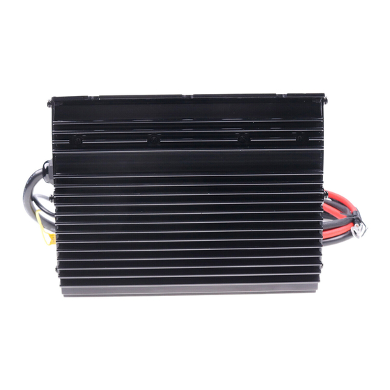
Summary of Contents for M&G 24V-25A
-
Page 2: Table Of Contents
Installation and User’s Manual for the Mo. 24V-25A High Frequency, Universal AC Input Battery Charger IMPORTANT: SAVE THESE INSTRUCTIONS! Read and follow all instructions before installing, operating, or servicing charger. Any deviation can cause serious and permanent damage. Installation and servicing must be performed by qualified personnel. -
Page 3: Charger Features
Charger Features: •Advanced high frequency design. - High effeciency. •25 ADC charging current. •Convection cooled with no moving parts. •Advanced microprocessor control. - Precise charging and termination algorithms. - Flooded type batteries and sealed gel (AGM) batteries. •Universal AC input. - 85-130/170-264 VAC, 47-63 Hz range. -
Page 4: Specifications
Specifications Specifications AC Input Ratings Voltage 90-130/180-260 VAC Max Current 9A @ 85V, 5A @ 170V Frequency 50-60 Hz Phase Single-Phase AC Input Tolerances Voltage 85-135/170-264 VAC Frequency 47-63 Hz DC Output Ratings Voltage Current AC Line Interlocking Environmental Operating Temperature -25 to 131°F (-31 to 55°C) Storage Temperature -40 to 185°F (-40 to 85°C) -
Page 5: Installation & Safety
Installation & Safety Installation • A wire loop provides for selection of battery types: flooded (Wet) type (do not cut the wire loop), sealed (AGM, Dry) and gel type (cut the wire loop and tape the wire ends back with electricians tape). •... - Page 6 Installation & Safety - cont. rating of the extension cable and meet all national and local electrical code • requirements. When attaching leads to battery terminals, be careful that tools do not short between battery terminals. Shorting between battery terminals may cause extreme arcing resulting in explosion or extreme heat that can cause burns.
-
Page 7: Operation
Operation (1) Make sure the yellow wire loop is prepared for the correct battery type. Flooded (wire loop not cut), sealed AGM and Gel (wire loop cut) (2) Connect the charger AC cable into a single phase AC socket with a nominal voltage rating of 100V, 110V, 115V, 120V, 220V, 230V, or 240V and a frequency rating of 50 or 60Hz. -
Page 8: Maintenance
Maintenance WARNING: Disconnect from AC voltage before doing any service. When plugged-in the AC wiring is an electric shock hazard. Disconnecting the DC output (connection to battery) near the batteries when the charger is ON may cause the batteries to explode resulting in serious injury or death. WARNING: Risk of an electric shock causing serious injury or death. - Page 9 LED Table for Troubleshooting Yellow Green #1 Green #2 Status Case 1 Normal Condition: AC Power is not connected to the charger. Normal Case 2 Condition: AC power on, charging in process. Case 3 ON/OFF Normal Condition: Charging is complete, charger is in maintenance mode. Not Normal Case 4 Possible cause:...
- Page 10 circuit, short circuit, or reverse polarity). STEP 3: Check if the voltage of the battery pack is greater than 6V. If Case 6 Blink Once in every Not Normal 8 seconds Possible cause: Charger is not charging. Reason? - battery voltage may be too hight. Troubleshooting - cont.
-
Page 11: Uninstalling The Charger
Troubleshooting - cont. BATTERIES DO NOT FULLY CHARGE If the batteries are charged overnight, make sure the AC supply is not being switched- off at night with other building items. NEW BATTERIES If batteries are new they sometimes need 20 to 30 charge/discharge cycles before they charge normally due to a process called plate formation.
Need help?
Do you have a question about the 24V-25A and is the answer not in the manual?
Questions and answers