Table of Contents
Advertisement
U
U
R
R
ECUMBENT
ECUMBENT
A
A
A
SSEMBLY
SSEMBLY
SSEMBLY
SERIAL NO. _______________________________________
Part No.
06042
NIVERSAL
NIVERSAL
I
I
NSTRUCTIONS
NSTRUCTIONS
U325
U325
E
E
XERCISE
XERCISE
O
/
O
O
/
FIRST EDITION
BIKE
BIKE
M
M
WNERS
WNERS
WNERS
PURCHASE DATE:_________________
Revision:
A
ANUAL
ANUAL
Date:
6 /05
Advertisement
Table of Contents

Related Manuals for LAMAR Universal U325


Summary of Contents for LAMAR Universal U325
- Page 1 U325 U325 NIVERSAL NIVERSAL BIKE BIKE ECUMBENT XERCISE ECUMBENT XERCISE SSEMBLY SSEMBLY NSTRUCTIONS WNERS WNERS ANUAL SSEMBLY WNERS NSTRUCTIONS ANUAL FIRST EDITION SERIAL NO. _______________________________________ PURCHASE DATE:_________________ Part No. Revision: Date: 06042 6 /05...
-
Page 2: Table Of Contents
ABLE OF ONTENTS Reference Information Page Hardware Reference Chart Parts Listing Product Exploded View Assembly Preparation Product Assembly Instruction 6-11 Computer Operation 12-14 Troubleshooting Preventative Maintenance Warranty Terms Product Registration MPORTANT RECAUTIONS WARNING: To reduce the risk of injury, please read the following precautions before assembling or using your new product. It is the responsibility of the owner to ensure that all users of this equipment are adequately informed of stated precautions. -
Page 3: Hardware Reference Chart
SSEMBLY ARDWARE EFERENCE HARDWARE PACK #1 #26 CARRIAGE BOLT #27 FLAT WASHER #27 FLAT WASHER #27 FLAT WASHER #28 ACORN NUT #29 TRUSS HEAD BOLT FRONT STABILIZER SEAT PAD #30 TRUSS HEAD BOLT #27 FLAT WASHER #28 ACORN NUT #26 CARRIAGE BOLT REAR STABILIZER SEAT BACK PAD HARDWARE PACK #2... -
Page 4: Parts Listing
ARTS EFERENCE U325 Assembly Parts Listing Item # Part Number Description QTY. 23062 Main Base Assembly 23065 Front Stabilizer Assembly 23066 Rear Stabilizer Assembly 05014 Left Pedal 05014 Right Pedal 03060 Seat Pad 03059 Seat Back Pad 05178 Seat Back Adjustment Knob 13002 Handlebar Assembly 13087... -
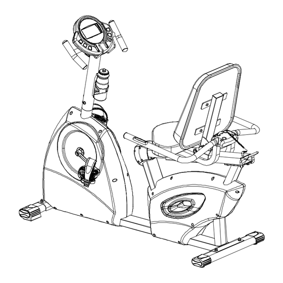
Page 5: Product Exploded View
XPLODED U325 Assembly Parts AC Power Adapter Customer Service 1-877-861-2181... -
Page 6: Assembly Preparation
SSEMBLY REPARATION NTRO RODUCT REPARATION ♦ To ensure ease of product assembly, please take time to verify the size and quantities of all required assembly hardware. Use the itemized parts listing and hardware chart for reference. ♦ The product assembly process has been documented in easy to follow stages. Please read all assembly instructions carefully. -
Page 7: Product Assembly Instruction
SSEMBLY NSTRUCTION SSEMBLY TAGE Attach Stabilizer Assemblies to the Base Assembly USE TOOL FRONT OF BIKE Note: Transport Wheels Face Outward DJUSTMENT EVELER FIGURE #1 (Reference enclosed hardware pack). Assembly Hardware Required: Carriage Bolt Qty. 4 Acorn Nut Qty. 4 Flat Washer Qty. - Page 8 SSEMBLY NSTRUCTION SSEMBLY TAGE Attach Pedals to the Base Assembly Use This End to Tighten the Pedals USE TOOL Note: Follow Assembly Instructions Carefully to Avoid Stripping Pedal Threads Assembly Hardware Required: (None Required) Assembly Description: A) Assemble the Left Pedal (#4) to the Left Crank Arm on the Base Assembly (#1). Thread the pedal onto the crank arm (counterclockwise) and securely tighten in place using the pedal wrench.
- Page 9 SSEMBLY NSTRUCTION SSEMBLY STAGE Attach Seat Pads to the Seat Frame USE TOOL FIGURE #2 FIGURE #3 Assembly Hardware Required: Flat Washer Qty. 8 Truss Head Socket Bolt Qty. 8 Truss Head Socket Bolt Qty. 4 Assembly Description: Cut the packaging cable ties and lock the Adjustable Seat Back Frame (#10) into an upright position using the Adjustment Knob (#8).
- Page 10 SSEMBLY NSTRUCTION SSEMBLY STAGE Attach Mast & H-Handlebar to the Main Base FIGURE #4 FIGURE #5 USE TOOL (*Hardware is Preinstalled in Base Assembly) Assembly Hardware Required: Truss Head Socket Bolts* Qty. 4 Spring Washer Qty. 2 Curved Washer* Qty. 4 Flat Washer Qty.
- Page 11 SSEMBLY NSTRUCTION SSEMBLY STAGE Attach Computer & Bottle Cage to the Handlebar Mast. USE TOOL Back of Computer Upper Data Cable Assembly Heart Rate Cable (*Hardware is Preinstalled in the Handlebar Mast & Computer) Assembly Hardware Required: Truss Screw* Qty. 4 Truss Screw* Qty.
- Page 12 SSEMBLY NSTRUCTION SSEMBLY STAGE Supplying Power to the Unit Front View of Base Assem- Assembly Hardware Needed: (None) Assembly Description: Note: This product requires AC voltage. Make sure bike is located near a wall outlet. (AC Adapter will have an approximate cord length of 6 feet).
-
Page 13: Computer Operation
OMPUTER PERATION OMPUTER NSTRUCTION COMPUTER START UP DESCRIPTION THE USER MAY PRESS ANY FUNCTION BUTTON OR START PEDALING TO ACTIVATE DISPLAY. ACTIVATION NOTE: BIKE MUST HAVE THE AC ADAPTER PLUGGED INTO A WALL OUTLET IN ORDER TO OPERATE PROPERLY. INTRO SCREENS 1) DISPLAY WILL SHOW “U1”. - Page 14 OMPUTER PERATION OMPUTER NSTRUCTION DISPLAY FUNCTIONS SPEED THE COMPUTER WILL REGISTER AND DISPLAY TRAINING SPEED (MPH). THE COMPUTER WILL READ AND DISPLAY PEDAL / DRIVE TRAIN ROTATIONS. DISTANCE THE COMPUTER ACCUMULATES TRAINING DISTANCE FROM 0.00 TO A MAXIMUM OF 99.90 MILES. EACH INCREMENT WILL BE DISPLAYED IN 0.01 MILE.
- Page 15 OMPUTER PERATION ROGRAMMING THE OMPUTER ROFILES (S The computer memory allows the storage of (4) individual training profiles. The user identification codes (U1, U2, U3, & U4) can be used to reference four preset training profiles. Once the computer is activated, a user identification code (U1, U2, U3, or U4) will appear on the display screen.
-
Page 16: Troubleshooting
ROUBLESHOOTING BASIC TROUBLESHOOTING TIPS PROBLEM DESCRIPTION SUGGESTED SOLUTION 1.1 CHECK AC ADAPTER FOR PROPER VOLTAGE OUTPUT (9-12 VDC). 1. NO DISPLAY INSPECT PLUG-IN RECEPTACLE ON THE FRONT OF THE UNIT FOR DAMAGE. CHECK CABLE CONNECTIONS: MAKE SURE CONNECTIONS ARE SECURE AND IN THE CORRECT ORIENTATION. -
Page 17: Preventative Maintenance
REVENTATIVE AINTENANCE Equipment Maintenance ♦ Use a dampened soft-cloth to wipe equipment free of perspiration after each use. Avoid getting excessive moisture on computer or electronic components. Do not use abrasive cleaners or petroleum-based solvents to clean equipment. ♦ Do not remove drive train shrouds or attempt any technical service on equipment without consulting an authorized service representative. -
Page 18: Warranty Terms
**Labor coverage excludes unauthorized repairs, service calls, and Fill out the enclosed warranty registration form and return to non-warranty related charges. LAMAR Health, Fitness & Sports, LLC within 30 days of product Exclusions & Limitations purchase. You can also register your product online. Along with product registration, keep copies of all product information for your Applied warranties are exclusive to LAMAR Health, Fitness &... -
Page 19: Product Registration
□ Yes □ No Thank you ! We appreciate your response. The information provided on this questionnaire is used exclusively by LAMAR Health, Fitness & Sports, LLC and will not be distributed to any other individuals or agencies regardless of purpose. - Page 20 STAMP LAMAR H LAMAR H LAMAR H , & S , & S , & S , LLC , LLC , LLC EALTH ITNESS PORTS EALTH EALTH ITNESS ITNESS PORTS PORTS 4699 N 4699 N #205 #205 4699 N #205...
Need help?
Do you have a question about the Universal U325 and is the answer not in the manual?
Questions and answers