Table of Contents
Advertisement
Advertisement
Table of Contents

Subscribe to Our Youtube Channel
Related Manuals for Bard Ultrasound System


Summary of Contents for Bard Ultrasound System
- Page 1 S it e~Ri te Vis i on* Ul tra sou nd Syste m Te chni cal Ma nu al 9770057...
- Page 2 Site~Rite Vision* Ultrasound System BF Type Equipment Attention, see instructions for use IPX1 Drip Proof Equipment Federal (U.S.A.) law restricts this device Rx Only to sale by or on the order of a physician. Medical Electrical Equipment Classified by CSA with respect to Electric Shock, Fire, and Mechanical Hazards only in accordance with UL60601-1 and CAN/CSA C22.2 No.
-
Page 3: Table Of Contents
Technical Manual Table of Contents Section Statement and Purpose System Overview Controls and Connections 2.1.1 Front Panel 2.1.2 Back Panel 2.1.3 Probe Attachment Hardware 2.2.1 Component Overview 2.2.2 Power System Software Roll Stand Adjustments Keyboard Adjustment Handle Adjustment Display Adjustment 3.3.1 Display Rotation 3.3.2... -
Page 4: Statement And Purpose
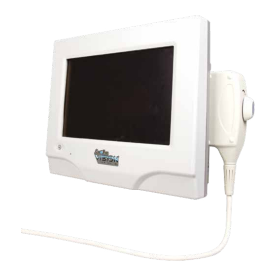
Refer to Site~Rite Vision* Ultrasound System Hardware & Operating Instructions for Use (IFU) for a list of warnings and precautions. System Overvie w Controls and Connections The Site~Rite Vision* Ultrasound System has user accessible features on the front and back panels, and an ultrasound probe connection on the side of the unit. 2.1.1... -
Page 5: Back Panel
Note: The VGA and Ethernet connections are consistent with VGA and Ethernet standards. Note: The printer power cable is identical on both ends. Both ends are compatible with both the printer and Site~Rite Vision* Ultrasound System. Note: The AC adapter cable must be inserted with the flat side of the connector toward VESA mount and the rounded side toward the USB ports. -
Page 6: Probe Attachment
Site~Rite Vision* Ultrasound System Table 2.1.2 Battery LED status Powered A/C System Power Battery Battery LED Status Adapter Detached Not in use Detached In use Attached Charging BLINK Attached Charging 2.1.3 Probe Attachment To connect the probe to the display: Step 1. -
Page 7: Hardware
A/C Adapter Power Supply The Site~Rite Vision* Ultrasound System is composed of several major components as depicted in Figure 2.2.1. See Table 2.2.1 for a functional description of each component. Table 2.2.1 Major Components of the Site~Rite Vision* Ultrasound System... -
Page 8: Power System
Site~Rite Vision* Ultrasound System 2.2.2 Power System Ethernet Connection (cable) AC Adapter (24V, 6.25A Output) AC Power Connection (cable) Power Control Module Computing 20V, 3.25 A Platform Power Supply Smart Battery Lithium Ion Charge Controller Battery 3.3V Power Supply (Microcontroller) 9.3V 4.0A... - Page 9 Table 2.2.2 Functional Description of Power System A/C adapter 24 VDC Functional Description Provides power to the Site~Rite Vision* Ultrasound System and turns the A/C Adapter 24 VDC microcontroller on. Turns power supply subsystems on and off depending on system inputs and Microcontroller changes of state.
- Page 10 Power Fusing: The Site~Rite Vision* Ultrasound System has several fuses which are not serviceable. These include fusing for the A/C adapter, the 24V input to the power control module, the 20V supply to the computing and display platform and the 9.3 volt supply to the printer. For power system failure contact Bard Access Systems’...
-
Page 11: Software
Site~Rite Vision* Ultrasound System. The application toolbar located in the bottom left corner of the screen acts as the central control point of the Site~Rite Vision* Ultrasound System. It launches and closes applications and offers configuration options. The operating instructions for each application are described in their respective instructions for use. -
Page 12: Roll Stand Adjustments
Site~Rite Vision* Ultrasound System Roll S tand Adjustm ents Keyboard Adjustment Rotation of the keyboard arm can be adjusted by tightening or loosening two fasteners on the bottom side of the keyboard arm with a ½ inch socket wrench. After the arm has been positioned, the fasteners can be tightened to lock the arm in position. -
Page 13: Handle Adjustment
Technical Manual Handle Adjustment The roll stand handle is designed to fold down for storage and fold up for transport. The hinge will function after the handle has been lifted up. To fold handle down: Step 1: Lift up the handle Step 2: Fold handle down The handle can be put in the transport position by reversing the steps. -
Page 14: Display Adjustment
Site~Rite Vision* Ultrasound System Display Adjustment 3.3.1 Display Rotation The roll stand is designed to allow the user to rotate the display 160° in the horizontal plane, 80° to the right and 80° to the left. To adjust the position of the display in the horizontal plane, turn the display to the desired position. -
Page 15: Locking The Casters
Technical Manual Locking the Casters There are three caster locks on the roll stand. Two are dark gray in color; one is light gray in color. The dark gray caster locks fix the position of the casters, but still allow the casters to roll. The light gray caster lock is a brake and fixes the position of the caster and prevents the castor and stand from rolling. -
Page 16: Technical Specifications
Site~Rite Vision* Ultrasound System Te chni c al Spe cif i cati o ns General Specifications 4.1.1 Operating and Storage Conditions Operating Temperature: 59ºF to 104ºF (10ºC to 40ºC) 0ºF to 104ºF (-18ºC to 40ºC) Storage Temperature: Operating Humidity: 5% to 85% Relative Humidity (non-condensing) -
Page 17: Emc Tables
Flicker IEC 61000-3-3 Complies Note: While the Site~Rite Vision* Ultrasound System is not classified to be used in a domestic environment, there may be a need for the health care professional to use the system for a limited duration. Warning: This system, with its applicable accessories, is intended for use by healthcare professionals only. If used in a domestic environment, this system may cause radio interference or may disrupt the operation of nearby equipment. - Page 18 Guidance and Manufacturer’s Declaration – Immunity The Site~Rite Vision* Ultrasound System is intended for use in the electromagnetic environment specified below. The customer or user of the Site~Rite Vision* Ultrasound System should ensure that it is used in such an environment. Electromagnetic Environment...
- Page 19 Guidance and Manufacturer’s Declaration – Emissions The Site~Rite Vision* Ultrasound System is intended for use in the electromagnetic environment specified below. The customer or user of the Site~Rite Vision* Ultrasound System should ensure that it is used in such an environment. Electromagnetic Environment...
-
Page 20: Leakage Current
Site~Rite Vision* Ultrasound System Leakage Current Leakage current does not exceed allowable limits according to IEC60601-1:1988, Medical Electrical Equipment, Part 1: General Requirements for Safety, including Amendment 1 and Amendment 2. Measured leakage currents are provided in the table below. -
Page 21: Repair And Troubleshooting
Repai r and Trouble sh o otin g The Site~Rite Vision* Ultrasound System does not require calibration or preventative maintenance and is not field serviceable. There are several simple troubleshooting steps that can be performed before the system should be returned for service. - Page 22 Site~Rite Vision* Ultrasound System Continued from previous page Check to ensure printer is on. Check to ensure printer has paper. Check printer power and USB connections. Ensure that the printer is Printer problems Printer error connected to the lowest USB port.
- Page 23 EC 2: Voltage Levels Out of Range No ultrasound image EC 3: System Initialization Error • Follow the recommended image optimization in Table 5.4 and 5.5. See the Site~Rite Vision* Ultrasound System Instructions for Use for additional information. Ultrasound Image Poor Image Quality •...
- Page 24 The MI and TI values should be monitored as these parameters are adjusted so that the lowest values of MI and TI are used that achieve the desired image. See the Site~Rite Vision* Ultrasound System instructions for use for further information regarding MI, TI and prudent use.
- Page 25 TI (Thermal Index) values. The MI and TI values should be monitored as these parameters are adjusted so that the lowest values of MI and TI are used that achieve the desired image. See the Site~Rite Vision* Ultrasound System instructions for use for further information regarding MI, TI and prudent use.
- Page 26 Fax: 1-(801)-522-4948 www.bardaccess.com * Bard, Sherlock, Sherlock 3CG and Site~Rite Vision are trademarks and/or registered trademarks of C. R. Bard, Inc. All other trademarks are the property of their respective owners. © 2010 C. R. Bard, Inc. All rights reserved.
Need help?
Do you have a question about the Ultrasound System and is the answer not in the manual?
Questions and answers