Advertisement
Table of Contents
- 1 General Safety Information
- 2 Receiving, Moving, and Unpacking
- 3 Installation
- 4 Electrical Connections
- 5 On/Off Switch
- 6 Start-Up Operation
- 7 Daily Maintenance
- 8 Weekly Maintenance
- 9 Monthly Maintenance
- 10 Engineering Data
- 11 Electrical Schematics
- 12 Replacement Parts
- 13 Item Description
- 14 Warranty
- Download this manual
Advertisement
Table of Contents

Summary of Contents for FScurtis RNP75
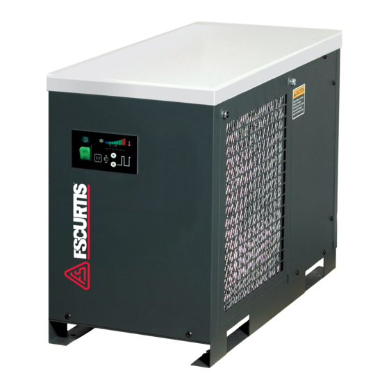
- Page 1 3227498 Rev. A AUGUST 2012 SERIES REFRIGERATED COMPRESSED AIR DRYERS OPERATOR MANUAL RNP75 RNP100 RNP125 RNP150 RNP200 RNP250 RNP300 RNP400 RNP500...
-
Page 2: General Safety Information
GENERAL SAFETY INFORMATION RECEIVING, MOVING, AND UNPACKING 1. PRESSURIZED DEVICES: A. RECEIVING This equipment is a pressure containing This shipment has been thoroughly checked, packed and device. inspected before leaving our plant. It was received in good condition by the carrier and was so acknowledged. •... -
Page 3: Installation
INSTALLATION Receiver Separator Ambient Air Temperature Locate the dryer indoors where the ambient air temperature will be between 45°F and 110°F. Intermittent operation at ambient temperatures up to 113°F will not damage the dryer but may result in a higher dew point or dryer shutdown Automatic Drain Aftercooler Oil Removal... -
Page 4: On/Off Switch
Dew Point Indicator Dryer System Monitor (DSM) (Models RNP75, RNP100, RNP125 and RNP150) (200 through 5000 scfm models) The Dryer System Monitor (DSM) has LED type dew point temperature indicators and electronic drain valve timing controls. - Page 5 Dryer System Monitor (Models RNP200, RNP250, RNP300, RNP400 and RNP500) 1. On/Off Switch: Press the top of the switch (I) to turn Six (6) LEDs that indicate dew point temperature the dryer on. Press the bottom of the switch (O) to according to the graphic scale above the LEDs.
-
Page 6: Start-Up Operation
START-UP/OPERATION SHUTDOWN Follow the procedure below to start your dryer. Failure When the dryer must be shutdown for maintenance or other to follow the prescribed start-up procedure will invalidate reasons, use the following procedure. the warranty. If problems arise during start-up, call your If electrical repairs must be made: distributor. -
Page 7: Weekly Maintenance
Weekly Maintenance Once the drain valve is disassembled, the following maintenance can be performed. Inspect the ambient air filter weekly and clean it if necessary. Inspect internal parts of valve body; clean or replace as Dirty air filters cause loss of efficiency and may result in required. - Page 8 FIELD SERVICE GUIDE Do not smoke when a refrigeration leak is suspected. Burning materials may decompose refrigerants, forming a toxic gas or acids that may cause serious injury and property damage. Problems most frequently encountered with refrigerated Before dismantling any part of the dryer or compressed dryers are water downstream of the dryer and excessive air system, completely vent the internal pressure to the pressure drop.
-
Page 9: Engineering Data
ENGINEERING DATA MODEL SPECIFICATIONS Rated Capacity a - (scfm) Inlet /Outlet Connections - (inches) 1-1/2 1-1/2 1-1/2 Dimensions Height - (inches) 20.1 20.6 20.6 20.6 30.0 30.0 29.9 29.9 31.5 Length - (inches) 19.7 28.3 28.3 28.3 35.4 35.4 37.4 37.4 41.3 Width - (inches) -
Page 10: Electrical Schematics
ELECTRICAL SCHEMATICS 115V/1PH/60Hz ON/OFF SWITCH WITH RUNNING LAMP F.P.S PTC STARTER COMP. ELECTRONIC MOTOR AUTO DRAIN OVERLOAD VALVE PROTECTOR Figure 1a 75 scfm models 115V / 1PH / 60Hz ON/OFF SWITCH WITH RUNNING LAMP F. P. S. PTC STARTER COMP. ELECTRONIC AUTO DRAIN VALVE MOTOR OVERLOAD... - Page 11 ELECTRICAL SCHEMATICS 115V/1PH/60Hz ON/OFF SWITCH WITH RUNNING LAMP Overload protector (OLP) F.P.S COMP. MOTOR Potential ELECTRONIC Relay P.R-b AUTO DRAIN VALVE Starting Capacitor Figure 1c 150 scfm models 460V/3Ø/60Hz TR 150VA 380V 440V 115V F1(2A) ON/OFF SWITCH WITH RUNNING LAMP H.P.S F.P.S * FUSE...
- Page 12 AIR AND REFRIGERANT FLOW SCHEMATICS MOISTURE SEPARATOR INTEGRATED BRAZED PLATE HEAT EXCHANGER CHILLER REHEATER (REF TO AIR HEAT EXCHANGER) (AIR TO AIR HEAT EXCHANGER) COMPRESSED AIR INLET COMPRESSED AIR OUTLET CAPILLARY TUBE DRAIN VALVE ELECTRONIC AUTO STRAINER DRAIN VALVE WITH TIMER HOT GAS BY-PASS VALVE AIR FLOW...
- Page 13 AIR AND REFRIGERANT FLOW SCHEMATICS MOISTURE SEPARATOR INTEGRATED BRAZED PLATE HEAT EXCHANGER REHEATER CHILLER (AIR TO AIR HEAT EXCHANGER) (REF TO AIR HEAT EXCHANGER) COMPRESSED AIR INLET COMPRESSED AIR OUTLET CAPILLARY TUBE DRAIN VALVE ELECTRONIC AUTO STRAINER DRAIN VALVE HOT GAS BY-PASS VALVE AIR FLOW REFRIGERANT CONDENSER...
-
Page 14: Replacement Parts
REPLACEMENT PARTS Item Description 75 scfm 100 scfm 125 scfm 150 scfm Refrigerant Compressor 3149274 3161249 3161249 3161250 Condenser (air-cooled 1283269 3161253 3161253 3161254 Fan Blades 3041954 3041954 3041954 3041954 Fan Motor 3161257 3161257 3161257 3161257 Filter Dryer 3161259 1283273 1283273 1283273 Solenoid Valve Assembly... -
Page 16: Warranty
AUTHORIZATION FROM THE SERVICE DEPARTMENT IS NECESSARY BEFORE MATERIAL IS RETURNED TO THE FACTORY OR IN-WARRANTY REPAIRS ARE MADE. SERVICE DEPARTMENT: (724) 746-1100 Curtis-Toledo, Inc. 1905 Kienlen Avenue, St. Louis Missouri 63133 phone: 314-383-1300 fax: 314-381-1439 email: info@curtistoledo.com WWW.FSCURTIS.COM...


Need help?
Do you have a question about the RNP75 and is the answer not in the manual?
Questions and answers