Table of Contents
Advertisement
Quick Links
Advertisement
Table of Contents

Related Manuals for Thermalec ZENITH RANGE 96kW

Summary of Contents for Thermalec ZENITH RANGE 96kW
- Page 1 Instruction Manual for Swimming Pool Heater ZENITH RANGE 96kW, 120kW, 144kW & 168kW Meddings Thermalec Ltd. Kingsley Close, East Way, Lee Mill Industrial Estate, Ivybridge, Devon, PL21 9LL, United Kingdom Tel: 01752 313343 Fax: 01752 313353 sales@thermalec.co.uk www.thermalec.co.uk...
-
Page 2: Table Of Contents
Zenith Range Instruction Manual Contents Preface ............................ii List of illustrations and drawings ....................iii Pictograms used in this manual ....................iv GENERAL ....................... 1 Heater construction ........................2 Heater operation ......................... 5 Heater technical details ......................5 Standards ..........................5 Materials of construction ...................... -
Page 3: Preface
Thermalec Pool & Spa Products is a member of Meddings Thermalec Ltd. We hope that you will be more than satisfied with your Thermalec® pool heater. At Thermalec, we always welcome customer feedback. Should you have any comments or suggestions regarding this equipment, please do not hesitate to contact us. -
Page 4: List Of Illustrations And Drawings
Zenith Range Instruction Manual List of illustrations and drawings Figure 1 External features of the Thermalec® Zenith ZHR Pool Heater ......2 Figure 2 Sectional model of a typical Thermalec® Pool Heater .......... 3 Figure 3 Suggested heater position on plant room flowsheet .......... 10 Figure 4 Water connection on a Thermalec®... -
Page 5: Pictograms Used In This Manual
Zenith Range Instruction Manual Pictograms used in this manual The following pictograms are used throughout this installation, operating and maintenance manual. Their purpose is to draw your attention to particularly important information. The type of information conveyed by the pictograms is described adjacent to each of them. - Page 6 Zenith Range Instruction Manual Page v...
-
Page 7: General
Zenith Range Instruction Manual 1. GENERAL Page 1... -
Page 8: Heater Construction
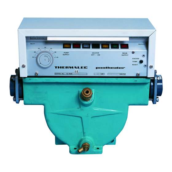
Zenith Range Instruction Manual Heater construction Figure 1 External features of the Thermalec® Zenith Pool Heater Electrical control gear enclosure Drain valve Circuit breakers on front fascia Support foot Control panel on front fascia Water inlet (default) Water outlet (default) - Page 9 Zenith Range Instruction Manual Heater construction (cont’d...) Figure 2 Sectional model of a typical Thermalec® Pool Heater Electrical control gear enclosure Inlet baffle plate uPVC element holding plate Temperature pocket Outlet baffle plate Water inlet overflow weir Water outlet nozzle (default)
- Page 10 Zenith Range Instruction Manual Heater construction (cont’d...) Thermalec® electric heaters are specifically designed for use with swimming pools and spas. The base of the heater is a fusion epoxy coated cast iron vessel through which the water from the swimming pool flows. The vessel is fitted with four safety pressure relief valves, a drain valve and the water inlet and outlet nozzles and its base is designed to support the heater on a flat, solid surface.
-
Page 11: Heater Operation
Heater technical details Standards Thermalec® pool and Spa heaters are CE marked and comply with: EU Council Directive 89/336/EEC & 93/068/EEC on Electromagnetic compatibility EU Council Machinery Directive 98/37/EEC EU Council Low Voltage Directive 2006/95/EEC &... -
Page 12: Materials Of Construction
Zenith Range Instruction Manual Materials of construction Heater vessel: Fusion epoxy coated cast iron Element holding plate: uPVC Gasket: Silicone rubber Water connections: uPVC socket (metric or imperial) Heater elements: Incoloy 825 sheath Electrical enclosure: Powder coated steel or leather grain coated steel Operating data Water inlet/outlet: Socket for 63 mm or 3”... -
Page 13: Electrical Data
Zenith Range Instruction Manual Control and indication(cont’d…) Status indicator lamps: Red (heater circuit breaker armed and powered), White (safety thermostat trip armed), Amber (pump interlock relay OK), 4 x Green (heating elements powered). X 1 Red EHOT. Electrical data Protection level: IP 21 Fuses: 2 x 2 Amp... -
Page 14: Installation
Zenith Range Instruction Manual 2. INSTALLATION Page 8... -
Page 15: Introduction
Zenith Range Instruction Manual Introduction The Thermalec Zenith heater is designed for use with swimming pools, spas and other similar installations. To prevent damage to the heater it must not be operated unless it is fully flooded with a sufficient flow of pool water. -
Page 16: Location
Zenith Range Instruction Manual Location The protection rating of the heater is lP21 and it should be installed in a weatherproof enclosure with good drainage. A suitable anti-condensation heater should be provided in high ambient humidity conditions, since moisture can damage electrical components. The heater must be installed in a cool, dry location. -
Page 17: Positioning And Piping Connection Of The Heater
It is not necessary to fit unions either side of the heater as the stub flanges are easily disconnected from the heater, by removing the nuts securing the aluminium backing flanges to the heater. In very tight installations, the studs themselves may be unscrewed. Figure 3 Water connection on a Thermalec® pool heater Page 11... -
Page 18: Direction Of Flow Through The Heater
Zenith Range Instruction Manual Positioning and piping connection of the heater(cont’d…) If required levelling screws can be used in the four holes in the base of the heater. These are used to level the heater. More importantly, they will stop the heater rocking on its base. - Page 19 APH 1319, together with arrangements for an override switch allowing the filter pump to be run continuously. Thermalec also produce a range of Pool Control Panels, which enable pumps, heating and all other pool items to be controlled from a single control box. All panels are made to order, to match the specific equipment.
- Page 20 Zenith Range Instruction Manual Figure 4 Drg. APH 13 19 Heater filter pump interlock Page 14...
-
Page 21: Operation
Zenith Range Instruction Manual 3. OPERATION Page 15... -
Page 22: Commissioning
Zenith Range Instruction Manual Commissioning First Start-up When using the heater for the first time (or after it has been isolated for the winter) it is vital that the heater is commissioned using the correct procedure. Failure to do so will result in serious damage to the heater. -
Page 23: Water Flowrate Through The Heater
Zenith Range Instruction Manual Water flowrate through the heater The flow rate of water through the heater should be set within the ranges given in the following table: Flow Rate 96 kW 120 kW 144 kW 168 kW Hard water maximum - use bypass above this rate 9000 gal/hr 9000 gal/hr... -
Page 24: Decommissioning
Zenith Range Instruction Manual Decommissioning Winterisation If the pool is to be closed over the winter, damage may be caused by chemically treated water and debris left standing in the heater vessel. The following procedure should be followed to preserve the integrity of the heater: a) Switch heater circuit breakers to OFF;... -
Page 25: Diagnostics
Zenith Range Instruction Manual Diagnostics Status Lamps The lamps will light in sequence in steps 1 to 7. The green lamps will only light (and the pool water be heated) when the other lamps are all lit. The following actions should be taken if any of these lamps are not lit: Controller Drift If, over time, the calibration of the temperature controller drifts such that the value set... -
Page 26: Warranty
& maintenance or by other neglect of the heater. In the event of a claim, Thermalec will at it sole discretion replace the heater, provide replacement parts or effect a repair at its factory or its local distributor.
Need help?
Do you have a question about the ZENITH RANGE 96kW and is the answer not in the manual?
Questions and answers