Advertisement
Quick Links
Advertisement

Summary of Contents for Autek Research QF-1A
- Page 1 Autek Research QF-1A Active Audio Filter User Manual...
-
Page 2: Initial Hookup
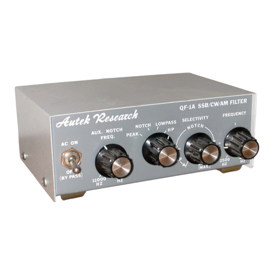
Your Autek QF-1A audio filter is the product of This switch and the Selectivity/Frequency controls several years of development by the originator of adjust the response of the main filter (all but the Aux commercial active audio filters for shortwave Notch). - Page 3 C. USEFUL ADJUSTMENTS PICKUP OF YOUR TRANSMITTED SIGNAL See Tables 1 and 2. This should be extremely rare with the QF-1A, as layout and RF bypass caps are excellent, and show no D. IN CASE OF TROUBLE sign of RF at 2 KW with the antenna 20 feet away and the cover off, in our tests.
- Page 4 Table 1 USEFUL ADJUSTMENTS Your QF-1A can “imitate” the response of virtually any filter with fixed response, at any price, and give an infinite number of other useful responses, as well. Truly, if the QF-1A can’t pull the signal out, no other filter can either! However, the QF-1A flexibility means that ever experienced operators will need some time to learn how to best use all the controls.
- Page 5 There is a conceivable use for almost all of the infinite number of settings under some conditions, and with some signals. The QF-1A will produce some improvement due to narrower bandwidth, especially on CW, but nothing dramatic on Line noise, voice.
- Page 6 Table 2 (Condensed Version of Table 1): Condition Function Selectivity Main Frequency PEAK or LP 8 o’clock or more For best copy Voice Splatter LOWPASS As on panel 7-11 o’clock Voice PEAK 7 to 9 o’clock For best clarity Voice 3 to 5 o’clock / 11 up 250 Hz / 11 up Whistle or other QRM...
-
Page 7: Warranty And Returns
Autek Research. This warranty is made to the original 1. Aux Notch Depth Alignment; Adjusted by the 10K consumer purchaser only, and is effective only upon trim-pot near the left side of the circuit board –... - Page 8 H. LATE NOTES K. CREDITS If you wish the QF-1A to drive a speaker in “bypass” Original documentation provided by Autek Research. you must obviously connect the QF-1A input to a rig Portions rewritten and PDF file compiled by AG4RC output which is capable of driving a speaker.
- Page 10 Inside View of Autek QF-1A (Component Placement) Illustration shown includes after market modifications: DC power input jack connected to ON/OFF switch, LED power “ON” indicator, and audio input jack. Illustration intended for standard component placement in reference to schematic diagram.
- Page 11 Bottom View of Autek QF-1A PC Board As illustrated: Top-Right control = R4 (Aux Notch) and Bottom-Left 14-pin IC = U3...
Need help?
Do you have a question about the QF-1A and is the answer not in the manual?
Questions and answers