Table of Contents
Advertisement
Quick Links
Advertisement
Table of Contents

Related Manuals for ASIX Forte

Summary of Contents for ASIX Forte
- Page 1 FORTE High-Speed USB Programmer Reference Manual...
- Page 2 ASIX s.r.o. reserves the right to make changes to this document, the latest version of which can be found on the Internet. ASIX s.r.o. renounces responsibility for any damage caused by the use of ASIX s.r.o. products.
-
Page 3: Table Of Contents
MSP430 / CC430 with TEST Pin, JTAG Interface Introduction MSP430 / CC430 without TEST Pin, JTAG Interface 1.1 Abbreviations & Terms Used MSP430 / CC430, SBW Interface FORTE TI (Chipcon) CCxxxx 2.1 Package Content STM8 2.2 Features ARM with SWD interface 2.3 Quick Start... - Page 4 4.5.3 Menus UP SOFTWARE File Menu 4.1 Abbreviations Used File ➙ New 4.2 Installation File ➙ Open... File ➙ Open next file... 4.3 Device Programming File ➙ Reload actual file 4.3.1 Programmer Selection File ➙ Save 4.3.2 Projects File ➙ Save as... 4.3.3 Device Type Selection File ➙...
- Page 5 ▸ Program configuration memory ▸ Beep after successful finishing ▸ Program differentially ▸ Beep after unsuccessful finishing ▸ Differential program data memory ▸ Turn off all sound for UP ▸ Mass Production ▸ Slower switching of voltage with ICSP Device ➙ Read ▸...
- Page 6 ▸ Mask ID positions during direct user input 4.5.4 Programmer Settings Window ▸ Configuration memory editor: show cfg FORTE Programmer Settings Window word instead of fuses Options ➙ Program settings ➙ Serial numbers Power supply from the programmer ▸ Serial numbers In idle state ▸...
- Page 7 Programming Connector Programmer 5.2 Settings 4.11 Updating UP 5.2.1 Default TCK signal frequency 4.12 Appendix A UP_DLL.DLL 5.2.2 Fast Clocks Option (FORTE only) 4.12.1 Data Types 5.2.3 RUNTEST without run_count (SVF only) 4.12.2 List of UP variables 5.2.4 RUNTEST Timing Multiply (both SVF and XSVF)
- Page 8 5.2.5 RUNTEST with run_count and no timing (both SVF and XSVF) 5.2.6 VPP PRESTO / P FORTE pin usage while running test (file) / after test completion 5.2.7 Default Settings Default Settings for FPGAs Default Settings for XC9500 Default Settings for AVR: 5.3 Running JTAG Player from Command Line TROUBLE-SHOOTING 6.1 Tips and Tricks...
-
Page 9: Introduction
Chapter 3 introduces the UP program, which is software the power-supply voltage on the VDD pin, used for controlling all ASIX programmers. You can find which can serve as either input or output procedures there for setting up the programmer prior to depending on the particular application. -
Page 10: Forte
VDD pin Thank you for buying the FORTE programmer made by ASIX s.r.o. It was a wise decision. Feel free to contact our GO button for quick function selection technical support in case of any questions or doubts. -
Page 11: Quick Start
Microcontrollers with ARM core – such as ATSAM3N2A or LPC2148. Start with installing the UP program. Its installer installs the USB driver for FORTE, too. You can find the installer Atmel AVR microcontrollers – all devices supporting on the supplied CD-ROM or on the web (the preferred "SPI Low Voltage Serial Downloading"... -
Page 12: Overcurrent Protection
USB Connection FORTE can power applications with a voltage from 1.8 V FORTE is controlled and powered through a USB port. It to 5.5 V. A controlled discharge resistor is incorporated communicates in the High-Speed mode (480 Mbps) / for faster transitions between different programming connected to a USB 2.0 port and in the Full-Speed mode /... -
Page 13: Controls And Connectors
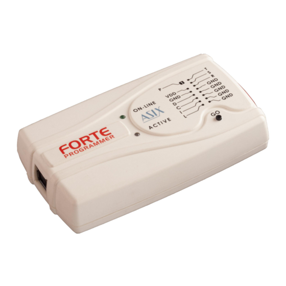
I/O, VPP signal input/output or VPP output power input/output signal grounding D, C, I, L, T, S, R I/O signal input/output Fig.2: The FORTE programmer Table 1: programming connector FORTE features two LEDs, a button, a connector for Page 13... -
Page 14: Go Button
A red color signals an error state. 2.6.1 Custom-made ON-LINE Connecting Cable The green LED informs you that FORTE is connected to a Should an application to be programmed have a non- computer and that the computer and the programmer compatible... -
Page 15: Programming In Zif Socket
A cable with a cross-section between 0.1 and 0.3 mm2 first connect FORTE to the target application, then may be used for making the custom connecting cable. connect FORTE to the USB and finally turn on the 2.6.2 Programming in ZIF application’s power supply. -
Page 16: Table Of Connections
Table of Connections Microwire UNI/O - CS AVR TPI ATxmega 8051 JTAG RESET RESET RESET SCIO ORG/(PRE) MOSI TPIDATA PDI_DATA MOSI TPICLK PDI_CLK MISO MISO Table 5: Connection list No.3 PSoC 1-Wire ARM SWD Table 3: Connection list No.1 XRST NRST MSP430 MSP430 SBW TI CCxxxx... -
Page 17: Connection Examples
8)PIC24 and dsPIC33 devices may be programmed using The following text presents examples of connections PE (Programming Executive) or using the standard between FORTE and the device being programmed. We method. Programming by means of PE is usually faster. use a notation according to the manufacturer datasheet of each particular device. -
Page 18: Avr With Tpi Interface (E.g. Attiny10)
5)Ticking the Open file with data memory automatically option in the File menu loads data for ATxmega with PDI Interface the data memory simultaneously with the code/main memory data. 6)Use the EESAVE fuse if preservation of data memory is required. If the EESAVE is active, choose Program all except data memory for programming, otherwise a warning appears at this place (blank check of data memory). -
Page 19: Cypress Psoc
3)FORTE can not program devices containing the letter “C” in their name, however, it supports devices with “S” MSP430 / CC430 with TEST Pin, in their name, of which some are compatible with the JTAG Interface “C” types. For example, AT89C2051 is not supported, but AT89S2051 is. -
Page 20: Msp430 / Cc430 Without Test Pin, Jtag Interface
4)Speed in the FORTE programmer settings window should be slow down if any external capacitor is connected to the device's reset pin. 5)The FORTE programmer also erases the Segment A of the information memory with the Erase Segment A option selected. Page 20... -
Page 21: Ti (Chipcon) Ccxxxx
TI (Chipcon) CCxxxx ARM with SWD interface Fig.16: (Chipcon Fig.18: ARM with SWD interface CCxxxx microcontroller) 1)ARM microcontrollers which do not have SWD interface are programmed via JTAG interface. STM8 I2C Memory Chips Fig.17: STM8 microcontroller Fig.19: I2C memory chips 1)The programmer uses an internal 2.2 kΩ... -
Page 22: Spi Memory Chips
1)Pin L determines the memory organization as either 8- bits or 16-bits per word. The user selects the required organization in the UP program and FORTE then sets this pin to the corresponding logic level. If this memory pin is firmly connected to the correct logic level inside Fig.20: SPI memory chips... -
Page 23: 1-Wire Interface
SWD interface, e.g. most of Cortex-M3 core chips, are programmed via this interface, see its connection. b)Clock source which is connected to the chip and its frequency must be set in the FORTE programmer settings window. Page 23... -
Page 24: Hpravr Adapter
LPC2xxx: For proper operation, it is required to tie both /RESET and /TRST pins to FORTE P output. Further, it is necessary to provide external pull-down resistor of 4.7 kΩ to 10 kΩ on the /RTCK pin. The LPC2xxx MCUs execute on-chip bootloader after reset. -
Page 25: Technical Specifications
2.8.2 Operating Specifications Important Warning Failure to respect these parameters may damage the programmer or the connected computer. Fig.27: HPRAVR adapter diagram Technical Specifications VDD feeding voltage 1.8 V to 5.5 V supplied by programmer VDD feeding voltage 1.8 V to 5.5 V supplied by application 2.8.1 Limit Values VDD external feeding voltage 1.2 V to 5.5 V... - Page 26 USB compatibility USB 2.0 High-Speed (480 Mbps) USB connector type B Dimensions 112 x 64 x 22 mm Weight 60 g Gross weight 230 g Table 8: Operating specifications The programmer can typically communicate at a lower application’s voltage at a reduced speed. Windows XP, Windows Vista, Windows 7, Windows 8, Windows 8.1 The UP software runs under Wine Page 26...
-
Page 27: Declaration Of Conformity
FORTE complies with the RoHS directive. 2.8.3 Declaration of Conformity Page 27... -
Page 28: Drivers
UP program installation. Windows 7 and later Start with installing the UP program. Its installer installs the USB driver for FORTE, too. You can find the installer on the supplied CD-ROM or on the web (the preferred option). Once the installation is complete, connect the FORTE programmer to your computer. -
Page 29: Linux
Please find a detailed manual at http://www.asix.net/ tools/supp_linux.htm Driver Updating FORTE communicates with the PC through a USB circuit produced by FTDI www.ftdichip.com, which also develops drivers for these circuits. The latest drivers are always included in the UP installation pack. -
Page 30: Up Software
(English or Czech), which programmer to work with (e.g. FORTE) and which port the programmer is connected to. If needed, the program can be uninstalled using the Add/ Remove Programs icon in the Control Panel or manually... -
Page 31: Projects
parameters. Once all required selections are made, save the project by choosing File ➙ Save proj ect... An existing project can be opened by choosing File ➙ Open proj ect..4.3.3 Device Type Selection Select the device type by choosing Device ➙ Select device or by double-clicking the device name displayed in the top right corner of the program window. -
Page 32: Longer Delay For Vdd Switching On/Off When
There is a great number of possible settings. If you are not sure that all the settings are correct, use the Load defaults button, which returns all the setting to the original (default) state. If you are updating UP to a new version, all the existing settings will be preserved. -
Page 33: Production Programming Settings
Settings for Programming Programmer Settings During Development Each time a particular programmer is selected (FORTE or PRESTO), the programmer settings window is displayed If you are frequently changing the content of the allowing the user to set the voltage used and some other... -
Page 34: Fuses And Working With Them
➙ Others ➙ Allow to change supply voltage If you cannot see these windows, activate them under level when it is on (FORTE only). the View menu. If a voltage is present at the VDD pin, you can stop the... -
Page 35: Differential Programming
Button displayed. Displaying of this warning message is frequently caused ASIX programmers feature a GO button, which allows the by a fault in the interconnection of the device and the user to trigger the programming process without a programmer. -
Page 36: Serial Numbers
4.4.3 Serial Numbers The Serial Numbers function programs the serial number or another sequence of characters in the selected memory location. Fig.34: Serial numbers Once the serial numbers are activated and their type set up under Options ➙ Program settings ➙ Serial Fig.33: Mass production numbers, a window with the current serial number opens offering the possibility to manually write a serial number... -
Page 37: Format Of Files With Serial Numbers
able to read it from a locked device, for example). A file for logging the programmed serial numbers can be selected under Options ➙ Program settings ➙ Serial Note: A word is understood as one memory position. numbers. The numbers themselves are logged in case of calculated serial numbers while their labels are logged in case of serial numbers taken from a file - see Format of Files with... -
Page 38: Example Of File With Serial Numbers
For example, b'10101010' means the same as h'AA', note d'170' or just AA. 'A' means d'65' (ASCII character itself). sn4: 0000 67 78 89 9A, 2100 04 02 03 04; Example record for PIC16F628A: sn5: 0000 78 89 9A AB, 2100 05 02 03 04; sn6: 0000 78 89 9A AB, 2100 06 02 03 04; 2100 05 55 54 means to save data 05h, 55h, 54h in sn7: 0000 78 89 9A AB, 2100 07 02 03 04; addresses 00 to 02 of a data memory. -
Page 39: Working With Calibration Memory In Devices With
3)Toolbar Working With Calibration 4)Currently selected programmer Memory in Devices With Flash 5)Currently selected device 6)Programmer settings window Memory 7)HEX editor window for code/main memory When these devices are erased, the content of their calibration memory is preserved. 8)HEX editor window for data memory 9)Configuration window If you really need to erase the calibration memory for some reason, you can do so by choosing Device ➙... -
Page 40: File Menu
underlined letter in the menu. For example, this command provides for merging of several .hex files (e.g. bootloader + program). menu consists following menus (categories): File ➙ Reload actual file File Menu Keyboard shortcut: Ctrl+R Edit Menu The program re-opens (i.e. re-reads from the disc) the currently open file. -
Page 41: File ➙ Import Data Memory From File
Important warning File ➙ Close project Such a file, regardless of its content, is read from the zero Keyboard shortcut: Shift+Ctrl+W address as if it contained only the data (EEPROM) The program terminates the work with the currently open memory. This means that a file generated normally by a project, saves the project file on the disc and returns to compiler cannot be correctly read using this command. -
Page 42: File ➙ Exit
File ➙ Exit Edit ➙ Text insert... Standard Windows keyboard shortcut: Alt+F4 This command saves a text in ASCII or in hexadecimal Keyboard shortcut: Alt+X format into a selected memory location. Ends of lines can be coded as NULL, CR, LF or CR+LF characters. Warning Individual bytes can be inserted as well as saved in If closing of the program is forced by the Turn... -
Page 43: View ➙ Data Memory
View ➙ Data memory Device Menu This command opens or closes the data memory HEX editor window. For more on HEX editors see HEX Editor Windows. Device ➙ Program View ➙ Configuration memory Keyboard shortcut: Shift+F5 This command opens or closes the configuration memory HEX editor window. -
Page 44: Program Configuration Memory
differential method. function identical with ▸ Program code/main memory differential programming of the code/main memory. A keyboard shortcut can be assigned in Options ➙ Key This command is available only for those devices that shortcuts. support such treatment (not all devices do). This command erases the code/main memory, checks the a device has the Code/Data Protection active, erasure, programs and checks the programming result. -
Page 45: Read Code/Main Memory
▸ Read code/main memory ▸ Verify code/main memory A keyboard shortcut can be assigned in Options ➙ Key A keyboard shortcut can be assigned in Options ➙ Key shortcuts shortcuts This command reads the content of the code/main This command compares the content of the code/main memory. -
Page 46: Erase Code/Main Memory
▸ Erase code/main memory ▸ Blank check of data memory A keyboard shortcut can be assigned in Options ➙ Key A keyboard shortcut can be assigned in Options ➙ Key shortcuts shortcuts This command erases the code/main memory. It cannot This command verifies whether the data memory is be used if Code/Data Protection is active. -
Page 47: Options Menu
▸ Ask before programming of OTP / Flash Options Menu / Code/Data Protection / differential A set of options determining which user confirmation Keyboard shortcut: Shift+F10 dialogs will or will not be displayed by the program. The Options menu holds all the possible settings of the The program asks just once except the Code/Data UP program. -
Page 48: Turn Off All Sound For Up
Both PRESTO FORTE feature overcurrent protection. This means that a test for excessive current of ▸ Do not erase device before approximately 100 mA in both power supply voltage and... -
Page 49: Verify With Two Supply Voltages
▸ Verify with two supply voltages ▸ Display descriptions on toolbar buttons This option is available only for FORTE and only for the Tool names are displayed next to individual tools in the internal power supply from the programmer. It allows you toolbar. -
Page 50: Automatically Check For Newer Versions Of
style settings before saving different project editors. as Little Endian) or as Big Endian (Never ask, load/ save as Big Endian). ▸ Automatically check for newer versions ▸ Save unused locations to .hex file of actual file If not all positions are saved, the final file is smaller, but it This option helps especially in debugging a program. -
Page 51: Read Data Memory Not From The File But
▸ Read data memory not from the file Options ➙ Program settings ➙ but from the device Colors If you want to make sure that the content of the data Keyboard shortcut: Shift+F10 memory does not get overwritten, use the ▸... -
Page 52: Show Only The Lowest Byte Of Word In Ascii
Serial Numbers. ▸ Show only the lowest byte of word in ASCII ▸ Serial numbers When this option is activated, the program shows the This tab allows you to choose whether serial numbers are ASCII translation of only the lowest byte of word, which to be used and if so then whether they should be read can be useful especially for PIC MCUs. -
Page 53: Number Base
decimal form). ▸ Fill with RETLW instruction ▸ Number base Individual words of the serial number can be filled with RETLW instruction in Microchip microcontrollers. This This option defines the base of the serial number option is available only if the serial number is located in characters. -
Page 54: Do Not Show Warning If Internal 5 V Is
If you approve the collision of supply voltages, it allows In order to protect the application connected to FORTE the programmer to connect its internal voltage to pin from damage, it is typically forbidden to change the... -
Page 55: Help ➙ List Of Supported Devices
Help ➙ ASIX website Reset This command opens www.asix.cz, the website of ASIX This button allows you to switch levels on the device's s.r.o. where you can find the latest drivers and manuals reset pin between the level required for reset and high for ASIX products. -
Page 56: Oscillator Frequency
Oscillator frequency I2C Bus Speed An external oscillator or a functional internal oscillator Select the maximum possible speed of the I C bus. The must be connected in the course of AVR microcontroller programmer switches on the internal pull-up of 2.4 kΩ programming. -
Page 57: Programming Method
The Reset button generates a resetting pulse. communicate with the device at a faster speed. At the programming, required value Programming Method communication memory including the clock speed is programmed. HVP Traditional programming is applied with 13 V present at VPP. This option has its effect only if the whole device is programmed. -
Page 58: Selecting An Area
between states of different cells to make it easy to see which cells have been read from a file, which have been Configuration Memory Editor successfully programmed, etc. Menu: View ➙ Display configuration memory Colors user-assigned. This especially recommended for workstations with displays/screens Keyboard shortcut to open the window: F12 displaying only a limited number of colors. -
Page 59: Running Up From Command Line
settings ➙ Editors ➙ Mask ID positions../ask To be used linked with /p. The program always asks if it is to continue before Running UP from launching the actual device programming even if the program settings specify not to ask. -
Page 60: Using A Project File
Example: 016709 or A6016709. up.exe file.hex /progname name This makes it possible to up.exe "C:\My Documents\Recent Projects\PIC select a programmer by its name such as \My latest project\flasher.hex" PRESTO or FORTE for example. /noboot This skips programming of the MSP430 boot memory. Page 60... -
Page 61: Device Programming
message receipt. Device Programming Messages must be sent to "up v1.x" class window. The up.exe /p file_name message type is always of WM_USER. up.exe /p file.hex Commands are identified by “wParam” while parameters by “lParam”. up.exe /p "C:\My Documents\Recent Projects\PIC \My latest project\flasher.hex" 4.6.2 Program Return Codes Problem-free execution. File error. File not found or incorrect file format, for example. -
Page 62: List Of Commands
4.7.1 List of Commands bit 3 = 1 boot memory (MSP430, CC430) verification Unless specified otherwise, the command returns to its below return value: bit 0 = 1 code/main memory bit 1 = 1 data memory (EEPROM) error, failed bit 2 = 1 configuration memory everything worked OK bit 3 = 1 boot memory (MSP430, CC430) Commands with a wParam of 1, 2, 3, 4, 5, 6 a 7 are... -
Page 63: Example Of Use
4 – more than 6 V Example of use return value FORTE: -1 - measuring error xx - measured voltage × 10 var example: 33 means 3.3 V window: HWND; begin UP program initialization window := FindWindow('up v1.x', nil); below Result := SendMessage(window, bit 1 = 1 reload settings (reload project/ini file or WM_USER, 0, 0);... -
Page 64: Up_Dll.dll Library
eName: PChar; Value:PChar): BOOL; stdcall; UP_DLL.DLL Library Function UP_SetIntValue_Wnd(WndClass:PChar; Valu eName: PChar; Value:integer): BOOL; stdcall; Thanks to this library strings can be exchanged with the UP program. Function UP_GetStrValue_Wnd(WndClass:PChar; Valu eName: PChar; Value: PChar; Size: integer): inte As the library needs to communicate with UP, the ger; stdcall; program must be running. UP_DLL cannot work on its own. Function UP_GetIntValue_Wnd(WndClass:PChar; Valu eName: PChar; var Value: integer): LongBool; std unit up_dll;... -
Page 65: Running More Than One Instance Of Up
The first instance of UP can be started the standard way from the start menu. Updates are free and are very easy. You can download a new program version from http://www.asix.net/tools/ Additional instances can be started from the command dwnld_up.htm and simply install it over the previous one line as up.exe /w "another up", for example. -
Page 66: Appendix A Up_Dll.dll
0 is false, other string value is true Selected programmer name 4.12.2 List of UP variables values are PREST, FORTE Prog.LoadFileBfgProg Prog.BusSpeed boolean integer If true, current file is reloaded before device (or its part) is... - Page 67 integer Prog.QBfrProgFlash boolean Serial number of programmer Question before programming flash devices LanguageFile string Prog.QBfrProg boolean Relative path to used languange file Question before programming OTP devices Project.File string Prog.QBfrDiffProg boolean Project file path Question before differential programming flash Project.Present devices) boolean Prog.QBfrProgCP...
- Page 68 code/main memory Serial integer data memory no serial numbers Serial.Retlw serial numbers are from external file boolean serial numbers are calculated If serial number is computed, if true, memory cells are filled with retlw instructions Serial.Step Serial.Addr integer integer Step of serial numbers If serial number is computed, address where to save Serial.File Serial.CPW...
- Page 69 lohi LoHi power supply during programming External 2.7 to 5.5 V Serial.Write.BeforeProg power supply during programming boolean Internal 5 V If true, current serial number is "written" into opened HEX SpecSettings.PREST.i2cSpeed editors just before programming the device. integer Serial.Write.AfterProg 100 kHz boolean 500 kHz If true, current serial number is "written"...
-
Page 70: Appendix B: Use Of Icsp
PRESTO programmer supports only fixed voltage of 4.13 13 V on pin P(VPP) in contrast to adjustable voltage within a range of 6.5 V to 17 V supported by FORTE. Please check limit voltage value on pin -MCLR/VPP of ICSP (In-Circuit Serial Programming) is a method of PIC the PIC device to be programmed by PRESTO. -
Page 71: Power Supply Options
The equivalent resistance is presented in table following overcurrent protection. PRESTO has a software protection table: in which an output gets disconnected by the running UP program having detected an overload. FORTE has a hardware protection, which does not depend on the control software. Programmer... -
Page 72: Icsp Connector
If UP points out an overcurrent error at VPP, a shorter ICSP cable may help (its maximum length is 15 cm). 4.13.3 ICSP Connector All ASIX programmers use a unified connector with 2.54 mm spacing of pins for programming with the ICSP Fig.37: Recommended connection of -MCLR/VPP pin algorithm. -
Page 73: Description Of Intel-Hex File Format
Record length. The configuration memory 4.14.2 Description of size is one word = 14 bit = 2 byte (byte alignment). Intel‑HEX File Format 400E Record address. The configuration memory Intel-HEX are text files consisting of lines. address is the word 2007h addressed by bytes, i.e. -
Page 74: Saving Device Type In .Hex File
Saving Device Type in .hex File Users frequently mistook the selected device type for the device type for which the .hex file was saved. To eliminate this, UP contains a function allowing you to save the device type in a file. The program adds one more line below the End of File: #PART=.. -
Page 75: Jtag Player
SVF (Serial Vector Format) is a file used for describing devices with the JTAG interface by means of PRESTO or high-level operations on the IEEE 1149.1 bus. FORTE programmers. Serial Vector Format (.svf) is the recommended file This utility is not part of the UP software installation pack... -
Page 76: State Of .Svf File Implementation
Supported TCK frequencies are 3 MHz, 1.5 MHz, 750 kHz and fragments of 1 MHz starting at 500 kHz for Some AVR devices do not support page by page PRESTO. FORTE adds 15 MHz, 10 MHz and 5 MHz on top programming. In such a case, the SVF file must be of these. -
Page 77: State Of Xsvf File Implementation
5.1.3 Programming be correctly described in the SVF format. Connector State of XSVF File The following table describes the functions of PRESTO's and FORTE's pins for programming by means of the JTAG Implementation interface. The XSVF file support has been implemented accordance with the "XAPP503, Appendix B: XSVF File... -
Page 78: Fast Clocks Option (Forte Only)
5.2.2 Fast Clocks Option Multiply (both SVF (FORTE only) and XSVF) This option is available only for the FORTE programmer. Recommended values: According to the JTAG specification, the signal at TDI is sampled at TCK's rising edge. However, should a higher for accurate timing specified in the SVF or XSVF file: 0% frequency be required (around 5 MHz or more), it may be... -
Page 79: Vpp Presto / P Forte Pin Usage While Running Test
XSVF): interpret as RUNTEST min_time with scale take much more time than what is specified in 1 MHz min_time. VPP PRESTO / P FORTE pin usage while running test The RUNTEST command containing run_count and (file): Tristate specifying max_time is executed at the currently running TCK frequency. -
Page 80: Running Jtag Player From Command Line
XSVF): interpret as RUNTEST min_time with scale execution of the last file could not be 1 MHz started VPP PRESTO / P FORTE pin usage while running test (file): Tristate VPP PRESTO / P FORTE pin usage after test completion: Tristate... -
Page 81: Trouble-Shooting
It also describes caused by unsuitably set fuses in the device. testing utilities for FORTE designed to check if the programmer is in good condition or damaged. Please go The length of the ICSP cable should not exceed 15 cm. - Page 82 Output signal quality can be verified by a voltmeter. The Generate waves option sends a periodical signal of approximately 1 kHz simultaneously to all outputs. Fig.38: FORTE Tester Neither reading of inputs nor setting of outputs works if there is no voltage at pin VDD.
-
Page 83: Document History
Document history Document Modifications made revision 2013-07-03 Newly created document 2013-12-18 Minor text corrections 2014-02-28 The NXP LPC2xxx family was added in the JTAG Interface chapter New command line parameter [/read] 2014-04-25 The STM8 family was added in the Connection Examples chapter 2014-07-01 The ARM SWD interface was added in the Connection Examples chapter...
Need help?
Do you have a question about the Forte and is the answer not in the manual?
Questions and answers