Table of Contents
Advertisement
Quick Links
Advertisement
Table of Contents
Troubleshooting

Summary of Contents for AMI Entertainment Rock-Star Lx
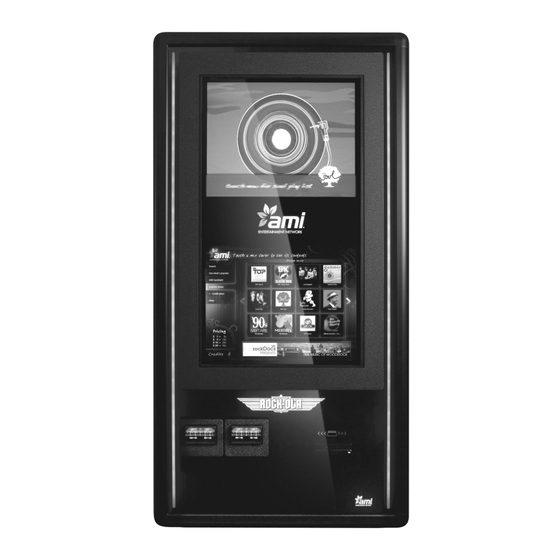
- Page 1 Installation & Owner’s Manual 22022611 Rev C...
-
Page 3: Table Of Contents
Table of Contents Important Safety Instructions ________________________________________ 2 Section A - Jukebox Specifications ___________________________________ 3 Section B - Placing the Rock-Star Lx Wall-Mounted Jukebox on Location ___ 4 Location Power and Warnings ________________________________________________ 5 Jukebox Power and Reset Switches ___________________________________________ 6... -
Page 4: Important Safety Instructions
Important Safety Instructions 1. Read these instructions. 10. Protect the power cord from being walked on or pinched, particularly plugs, convenience 2. Keep these instructions. receptacles, and the point where they exit from the apparatus. 3. Heed all warnings. 4. Follow all instructions. 11. -
Page 5: Section A - Jukebox Specifications
Section A - Jukebox Specifications Rock-Star Lx Rock-Star Lx Dimensions: Uncrated: Height 48” Width 25.75” Depth 10.75” Crated: Height 52” Width 31” Depth 24” Weight: Uncrated 155 lbs. Crated 170 lbs. Amplifier: Output Power: 1600 Wrms (Standard) (Optional) 2600 Wrms... -
Page 6: Section B - Placing The Rock-Star Lx Wall-Mounted Jukebox On Location
Section B - Placing the Rock-Star Lx Wall-Mounted Jukebox on Location • Location Power and Warnings • Jukebox Power and Reset Switches • Wall Mounting Instructions • IR Remote Installation Instructions • Hard Drive Installation Instructions • Testing the Unit •... - Page 7 Location Power and Warnings The jukebox must have a clean source of properly-phased and grounded 115VAC power at 10 amps max. This MUST be provided 24 hours a day, 7 days a week. The outlet the jukebox is connected to must NOT be controlled by a switch, nor can the circuit breaker feeding it be shut off at night.
- Page 8 Jukebox Power and Reset Switches The Rock-Star Lx is powered from a standard Hard Power Down 115VAC wall plug using the provided power cord. When the jukebox power cord is unplugged or the Inside the jukebox, power is routed to a Power...
- Page 9 NOTE: If the wall is concrete, cinder block, brick, or uses metal wall studs, then the appropriate fasteners For easier installation, the Rock-Star Lx is shipped must be used. At least 4” heavy duty fasteners (one with the front door detached from the cabinet. After in each corner) must be employed.
- Page 10 WARNING The next step requires two people who can safely lift 170 lbs. 7. The front door is secured using slide hinges, 5. Lift the cabinet onto the wall bracket. It will have which require no tools to attach. To attach the to be lifted about 2”...
- Page 11 8. Using Figure 7-B, locate the free ends of the 3 9. Using Figure 7-B, locate the free ends of the credit LCD cables, 2 LED cables and bill acceptor cable card reader and ground wire cables on the door. inside the cabinet.
- Page 12 IR Remote Installation Instructions The Rock-Star Lx comes with an IR remote (located The POWER button turns the lights, the LCD display, in the Handy Pack). To install, plug the provided the bill acceptor(s), and the credit card reader cable into the provided IR remote receiver (see ON/OFF.
- Page 13 After the jukebox has made its initial connection to These cables will be routed out of the bottom the AMI Entertainment Network, it must continue to of the computer core near the hard drive. connect at least once every 7 days to validate its Connect these cables to the hard drive as licenses or the jukebox will cease to play selections.
- Page 14 Testing the Unit Testing the Network 3. Touch Credit Device Tests. 4. Touch the box next to “Bill Acceptor” and “Credit When all of the network connections have been Card” (if applicable) to put a check in the box and made, boot up the jukebox.
- Page 15 LED Lighting Controller The LED Control Assembly (see Figure 10-B) controls all of the decorative lighting for the jukebox. It controls 56 separate ultra-bright RGB LEDs. The LED Control Assembly provides adjustments for the following features: SPEED 1. Choice of 10 different color and pattern settings. 2.
- Page 16 DIP Switches on LED Lighting Controller for Color and Light Pattern Settings Pattern Rainbow Effect (fades from one color to the next) Color Cycle (Aqua, Purple, Blue, Yellow, Green, Red) This pattern is used when ‘Beat to the Music’ is active and a song is playing. Single Color Blue/Green (Aqua) Single Color Red/Blue (Purple) Single Color Blue...
-
Page 17: Section C - Audio Description & Operation
Section C - Audio Description & Operation • Audio System Description • Audio System Features and Settings • Sound & Speaker Set Up • Connecting to Additional Power Amplifiers • Connecting a Paging Microphone • Connecting Speakers to an Audio Transformer •... - Page 18 Figure 1-C – Rock-Ola / Peavey Sound System for Rock-Star Lx The audio system in the Rock-Star Lx jukebox is a amplifier. The standard IR remote control may be result of collaboration with one of the best commercial configured to operate the internal and external and musical instrument amplifier manufacturers in the channels separately.
- Page 19 Audio System Features and Settings The SyberSonic audio system is preset at the factory Equalizer – This is a software setting that changes for optimum operation; however, some adjustment speaker tone by increasing or decreasing the may be required to achieve the best sound or response (gain) of a particular frequency range.
-
Page 20: Sound & Speaker Set Up
Sound & Speaker Set Up The Rock-Star Lx incorporates a 1600 Wrms Power The figure below is a representation of the Audio Amplifier for the speakers. In its default configuration, Transformer Assembly. Its purpose is to match the the Power Amplifier is connected to the Pre-Amplifier... -
Page 21: Connecting To Additional Power Amplifiers Or "House" Systems
Connecting to Additional Power Amplifiers or “House” Systems Connecting a Paging Microphone To yield 3 or 4-zone mono or 2-zone stereo, the jukebox The Advanced SyberSonic Pre-Amplifier can accept may be connected to an additional power amplifier. To virtually any paging microphone. Pictured below are do so, leave the amplifier inside the jukebox connected wiring diagrams for the most common paging kits. -
Page 22: Connecting Speakers To An Audio Transformer
Connecting Speakers to an Audio Transformer Determining which tap(s) of the Audio Transformer to If distributing power, simply add the amount of use may be accomplished two ways: impedance power consumed for each connected speaker and matching, or distributing power. make sure the total is 450 Watts or less. -
Page 23: Power Delivered To Each Speaker
Power delivered to each speaker WARNING Be sure the maximum power rating of the speaker used is higher than the maximum power delivered. Figure 3-C Page 21... -
Page 24: Setting Volume Zones
Setting Volume Zones The Rock-Star Lx Digital Downloading Jukeboxes Signal Inputs and Outputs have the capability of controlling up to four The Digital SyberSonic Pre-Amplifier has five (5) sets independent volume zones when using Rowe’s IR of RCA type jacks. -
Page 25: Section D - Service & Maintenance
Section D - Service & Maintenance • Routine Maintenance Schedule Page 23... -
Page 26: Recommended Routine Maintenance
3. Brush* dirt from the amplifier fan. Verify fan airflow is reduced by at least 25%. There are several operation. cooling fans in the Rock-Star Lx jukebox (see Figure 4. Brush* dirt from the fan located inside the 1-D, next page). - Page 27 Fan Locations NOTE: The fan at the top of the front door is not shown in diagram below. Figure 1-D – Inside View of Cabinet Page 25...
-
Page 28: Section E - Parts Catalog
Section E - Parts Catalog • Front Door • Bill Acceptor Assemblies • Inside and Outside Cabinet • LCD Assembly • Electronic Components • Harnesses • Accessories Page 26... -
Page 29: Front Door
Front Door See "Bill Acceptor Assemblies" for parts details OUTSIDE VIEW Page 27... - Page 30 Front Door INSIDE VIEW Page 28...
- Page 31 Front Door 5 25 SECTION A-A INSIDE VIEW – SHOWN WITHOUT BACK COVER, LCD & BRACKET ASSEMBLY Page 29...
- Page 32 Front Door Ref. Qty. Part # Description 61194001 Bezel – 32" Display 34099501 Bezel – Card Reader 34098501 Bracket – Display Clamp 22312001 Bracket – Latch Hook 34098901 Bracket – Light Block 22317001 Bracket – LED Mounting 22314001 Bracket – Panel Retainer 22315001 Bracket –...
-
Page 33: Bill Acceptor Assemblies
Bill Acceptor Assemblies 22316001 – Single MEI Bill Acceptor (700 bill) 22316003 – Single Coinco Bill Acceptor (700 bill) Ref. Qty. Part # Description Ref. Qty. Part # Description 22135613 B/A – MEI Downstack 22135614 B/A – Coinco Downstack 34098701 Bezel –... -
Page 34: Inside And Outside Cabinet
Inside and Outside Cabinet INSIDE CABINET LOCK PARTS Page 32... - Page 35 Inside and Outside Cabinet OUTSIDE CABINET Ref. Part # Description Ref. Part # Description ST-11530 Bushing, Wire Access Holes 40955703 Rowelink Controller 70251-A Audio Distribution Assembly 70260-1A Core Assembly ST-11527 Hex Bolt ½-13 x ¾ 28280004 Router 70261-1A Pre-Amplifier Assembly 61170003 Amplifier 40982101...
-
Page 36: Lcd Assembly
LCD Assembly FLANGE TO THE OUTSIDE; BOTH SIDES OUTSIDE VIEW INSIDE VIEW Ref. Qty. Part # Description 61194201 Display Mounting Bracket 61194301 LED CBA Mounting Bracket 40976601 Inner LED Lights Circuit Board Assembly 40976602 Outer LED Lights Circuit Board Assembly 28254502 M4 X 10 Phil Pan Head Screw 70500004... -
Page 37: Electronic Components
Electronic Components Power Supply Assembly 40982101 Ref. Qty. Part # Description Ref. Qty. Part # Description 34099701 Circuit Board Assembly 25241206 Circuit Board Insulator 21375903 Convenience Outlet - 3 Wire 80403006 #8-32 X 3/8 Phillips Screw 22118703 Power Inlet – IEC 320 C-14 Components not shown above: 70073618 Circuit Breaker –... - Page 38 Electronic Components Core Assembly w/ AMI System Interface 70260-1A Ref. Qty. Part Number Description Ref. Qty. Part Number Description Computer Core 61176513 61188002 Core and Rowelink Bracket Assembly Screw - #6-32 X ¼” Phil ST-06348 87842300 Keps Nut - #6-32 Pan Head (inside cover) Screw - #6-32 X ¼”...
-
Page 39: Harnesses
Harnesses 1 . 6 1 9 7 2 - A -L F T o P in 1 R e d S trip e 1 0 .0 " 2 . 6 1 9 7 3 - A -L F R e d / Y e l R e d / O rg R e d /B rn R e d / W h t... - Page 40 Harnesses 5 . 6 2 0 6 0 -A -L F 6 2 0 5 9 -A -L F 6 2 0 6 0 -A -LF 6 2 0 5 9 -A -LF 6 . 3 4 0 9 4 3 5 0 7 .
- Page 41 Harnesses 10. 34022338 11. 34022342 12. 34033235 13. 34037940 14. 34100303 15. 34099901 Page 39...
- Page 42 Harnesses Item Part number Description 61972-A-LF Rowelink Serial Harness 61973-A-LF Rowelink Harness 58902-A Communication Harness, 12” 60842-2A-LF Cabinet Fans Harness 62059-A-LF and Audio Harness, Dual RCA, 6” and 62060-A-LF Audio Isolator Harness, 24” 34094350 Peavey Audio Input Harness 62009-A-LF Wired Volume Control Harness, 24” 58923-A-LF Ground Strap, 7”...
-
Page 43: Accessories
Accessories Part Number Description 22118911 Handy Pack (contains the following) 21958306 IR Transmitter 40846302 IR Receiver 34037905 IR Receiver Cable 22310001 Cabinet Feet 58620-LF Power Cord 22022611 Installation and Owner’s Manual 70004-1A 2-Channel Remote Control 62009-A-LF Remote Control Cable ST-11327 #8 x 1 1/2”... -
Page 44: Section F - Troubleshooting
Section F - Troubleshooting • LED Indicators • Troubleshooting Chart • Connection Diagrams • Contact Information Page 42... - Page 45 LED Indicators The LEDs are described below and can help you isolate a problem. For Rock-Ola’s Digital SyberSonic Pre-Amp LED indicators, see page 22. ROWELINK CONTROLLER 5 VDC, 12 VDC, 24 VDC, and 24 VAC LED’s Should be on. On when there is power to the ROWELINK CONTROLLER. IR RCV LED Flashes whenever any IR signal is seen by the IR RECEIVER.
-
Page 46: Troubleshooting Charts
Troubleshooting Charts The best way to isolate a problem is to determine its cause. The following charts should help to narrow down which module is failing and whether it can be fixed or it needs to be replaced. Start with finding the “Problem” column that relates the closest to the problem you are experiencing and then match it to the closest “Symptom”. - Page 47 (jack) and the router. 3. All the lights on the front of the router are ON. 4. The router was shut off or lost power. 5. The Internet service provider (ISP) is down. 6. The AMI Entertainment server is down. Page 45...
-
Page 48: Connection Diagrams
Connection Diagrams TO ROWELINK TO ROWELINK CONTROLLER ASSY CONTROLLER ASSY 40955703 P6 SHEET 2 40955703 P4 SHEET 2 AND CORE COMPUTER ATX PWR SUP SHEET 4 60842-2A-LF (part of assy 70260-1A) FA N1- 60820-LF FA N1+ FA N1-TA CH PERIPHERA L R/BR FA N2- INTERFA CE... - Page 49 C OIN A C OM 61342-A-LF C OIN A SIG 70189-1A ASSY ROWELINK COIN +9 VDC (cba 62016-A) CA NCEL 9 V COMMON LED A ANODE SWITCHES DISCRETE ROWELINK A LED B C ATHODE VOLUME WIRE OPTIONAL ROWELINK B C OIN B SIG PA USE STATUS C OIN B C OM...
-
Page 50: Output Transformer Assembly
OUTPUT-XFMR-ASSY 70251-A OHMS R-CH 1/16 R-CH L-CH TO COMPUTER CORE AUDIO OUTPUT SHEET 4 62060-A-LF 1/16 OHMS 62059-A-LF L-CH CH-A OUTPUT CH-B BGM- IN MA IN- IN PREAMP ASSY CH-A PEAVEY 70261-1A 70261-A INPUT RS485 (cba 62004-A) CH-B PERIPHERAL FIXED-OUT EXT-OUT INTERFACE 61190101... - Page 51 MO DEM PROVIDED BY CUSTO MER WHEN REQUIRED POWER RJ12 TO ISP PROVIDER MODEM 28280004 D-LINK 4-PORT WBR 1310 WAN or ETHERNET RO UTER WIRELESS ETHERNET ROUTER TO JUKEBOX ADAPTER SPARE PORT SPA RE PORT SPA RE PORT COMPUTER MOUSE MINI-DIN 6 ETHERNET TO ROUTER OUTLET...
-
Page 52: Contact Information
Contact Information For additional assistance, after contacting your distributor, contact: AMI Entertainment Network, Inc. USA and Canada call toll-free: 1-877-762-6765 (1-877-ROC-N-ROL) Outside the USA and Canada call: (616) 243-3633 E-mail: support@amientertainment.net www.amientertainment.com Page 50...
Need help?
Do you have a question about the Rock-Star Lx and is the answer not in the manual?
Questions and answers