Advertisement
Table of Contents
- 1 Table of Contents
- 2 Important Safe Operation Practices
- 3 Maintenance and Storage
- 4 Assembling Your Chipper Shredder Vacuum
- 5 Know Your Chipper Shredder Vacuum
- 6 Operating Your Chipper Shredder Vacuum
- 7 Adjusting Your Chipper Shredder Vacuum
- 8 Maintaining Your Chipper Shredder Vacuum
- 9 Troubleshooting
- 10 Parts List
- 11 Cleveland, Ohio
- Download this manual
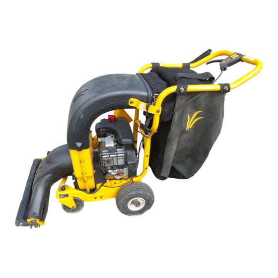
OPERATOR'S MANUAL
Chipper Shredder
Vacuum
Model Number
CSV240
IMPORTANT: READ SAFETY RULES AND INSTRUCTIONS CAREFULLY
Warning:
This unit is equipped with an internal combustion engine and should not be used on or near any unimproved forest-
covered, brush-covered or grass-covered land unless the engine's exhaust system is equipped with a spark arrester meeting
applicable local or state laws (if any). If a spark arrester is used, it should be maintained in effective working order by the operator.
In the State of California the above is required by law (Section 4442 of the California Public Resources Code). Other states may have
similar laws. Federal laws apply on federal lands. A spark arrester for the muffler is available through your nearest engine authorized
service dealer or contact the service department, P.O. Box 368023 Cleveland, Ohio 44136-9722.
CUB CADET CORP. P.O. BOX 368023 CLEVELAND, OHIO 44136-9722
770-10010C.fm
PRINTED IN U.S.A.
FORM NO.
(4/01)
Advertisement
Table of Contents

Subscribe to Our Youtube Channel
Related Manuals for Cub Cadet CSV240

Summary of Contents for Cub Cadet CSV240
- Page 1 Federal laws apply on federal lands. A spark arrester for the muffler is available through your nearest engine authorized service dealer or contact the service department, P.O. Box 368023 Cleveland, Ohio 44136-9722. CUB CADET CORP. P.O. BOX 368023 CLEVELAND, OHIO 44136-9722 770-10010C.fm PRINTED IN U.S.A.
-
Page 2: Table Of Contents
(Model Number) (Serial Number) Copy the model number here: Copy the serial number here: CUB CADET CORP. P.O. BOX 368023 CLEVELAND, OHIO 44136 CALLING CUSTOMER SUPPORT If you have difficulty assembling this product or have any questions regarding the controls, operation or maintenance of this unit, please call the Customer Dealer Referral Line. -
Page 3: Important Safe Operation Practices
SECTION 1: IMPORTANT SAFE OPERATION PRACTICES WARNING: This symbol points out important safety instructions which, if not followed, could endanger the personal safety and/or property of yourself and others. Read and follow all instructions in this manual before attempting to operate this machine. Failure to comply with these instructions may result in personal injury. -
Page 4: Maintenance And Storage
To reduce a fire hazard, keep machine free 11. Keep all guards, deflectors and safety devices in of grass, leaves, or other debris build-up. place and operating properly. Clean up oil or fuel spillage and remove any 12. Keep your face and body back and to the side of fuel soaked debris. -
Page 5: Assembling Your Chipper Shredder Vacuum
WARNING: - YOUR RESPONSIBILITY: Restrict the use of this power machine to persons who read, understand and follow the warnings and instructions in this manual and on the machine. NOTE: Not all safety labels shown may apply to your chipper shredder vacuum. SECTION 2: ASSEMBLING YOUR CHIPPER SHREDDER VACUUM This unit is shipped without gasoline or oil WARNING: Before setting up your chipper... -
Page 6: Know Your Chipper Shredder Vacuum
Attaching The Nozzle Bag Opening Discharge • Remove three wing nuts from the front of the Chute chipper shredder vacuum. • Place nozzle in position over the three studs on unit and secure with wing nuts just removed. See Figure 2. Wing Wing Nuts... -
Page 7: Operating Your Chipper Shredder Vacuum
Throttle Control Lever (Not Shown) Engine Controls The throttle control lever is located on the engine. It See the separate engine manual for the location and controls the engine’s speed and stops the engine. See function of the controls on the engine. separate engine manual packed with unit for details. - Page 8 Using the Chipper Shredder Vacuum • Engines with primer: Prime engine as instructed in separate engine Place both hands on top of upper handle to push unit manual. over yard waste. Yard waste such as leaves and pine • The throttle control lever is located on the engine. needles can be vacuumed up through the nozzle for Move engine throttle control lever to FAST or shredding.
-
Page 9: Adjusting Your Chipper Shredder Vacuum
SECTION 5: ADJUSTING YOUR CHIPPER SHREDDER VACUUM Drive Clutch Cable Adjustment WARNING: Do not at any time make any adjustments without first stopping engine, Adjust the drive clutch control if the chipper shredder disconnecting spark plug wire, vacuum moves forward with the drive clutch control grounding it against the engine. -
Page 10: Maintaining Your Chipper Shredder Vacuum
SECTION 6: MAINTAINING YOUR CHIPPER SHREDDER VACUUM Lubrication WARNING: Before performing any mainte- (Refer to Figure 5) nance or repairs, stop the engine, wait Wheels: Lubricate the rear wheels with light oil once a until the machine comes to a complete season. - Page 11 Access Plate Hex Bolt Flat Washer Hex Nut Self-Tapping Screws Lock Nuts Discharge Chute Self-Tapping Belt Cover Screws Hex Bolts Figure 11 Hex Nuts WARNING: Use caution when replacing the blades, wear heavy gloves to avoid a Flail Screen contact injury with the weld bolts or the housing while loosening or tightening the blades.
- Page 12 Safety Switch Hex Bolts Self-Tapping Screw Lower Belt Guard Hex Bolts Self-Tapping Screws Figure 14 Figure 12 • Insert the new belt between the frame and • Remove the safety switch from the front of the outer transmission pulley. It may be necessary to use a housing by removing the two self-tapping screws.
- Page 13 • Secure the impeller assembly to the crankshaft using the hex bolt, lock washer, and flat washer Outer previously removed. Torque the bolt to 550 in. lbs. Housing to 700 in. lbs. • Place the housing blades against the inner housing.
-
Page 14: Troubleshooting
SECTION 7: TROUBLESHOOTING Problem Cause Remedy Engine fails to start 1. Spark plug wire disconnected. 1. Connect wire to spark plug. 2. Fuel tank empty or stale fuel. 2. Fill tank with clean, fresh gasoline. 3. Throttle control lever not in correct 3. - Page 15 NOTES...
-
Page 16: Parts List
Model CSV240... - Page 17 Model CSV240 Ref. Part No. Part Description 681-0095 Chipper Chute 712-3010 Hex Nut 5/16-18 736-0242 Bell Washer .340 ID x .872 OD 731-1838A Discharge Chute 764-0492 631-0070 Nozzle Assembly 731-1831 Nozzle Flap 710-0969 Screw 720-0190 Height Adjustment Knob 732-0754 Spring Lever...
- Page 18 Model CSV240...
- Page 19 Model CSV240 Ref. Ref. Part No. Part Description Part No. Part Description 681-0116 Impeller Ass’y Complete 681-0098 Housing Ass’y Inner Flail 719-0329 Flail Blade 781-0599 Upper Shredder Blade 715-0166 Spiral Pin 736-0119 Lock Washer 5/16 681-0107 Impeller Assembly 710-0772 Hex Cap Screw 5/16-18 x 2...
- Page 20 Model CSV240...
- Page 21 Model CSV240 Ref. Ref. Part No. Part Description Part No. Part Description 781-0677 Chain Case LH 741-0414 Flange Bearing .629 ID 781-0676 Chain Case RH 741-0415 Flange Bearing .566 ID 754-0457 V-Belt 719-0325 Lower Housing 748-0313 Spacer 748-0373 Flange Bearing .503 ID...
- Page 22 Model CSV240...
- Page 23 Model CSV240 Ref. Ref. Part No. Part Description Part No. Part Description 749-1095 Upper Handle 710-0157 Hex Cap Screw 5/16-24 x .75 1539-019 Push Nut 710-3103 Hex Cap Screw 5/16-18 x 1.75 711-0737 Stud Pin .250 x 1.75 749-1094 Lower Push Handle 746-0714 Clutch Cable 56"...
-
Page 24: Cleveland, Ohio
How to obtain service Contact your authorized Cub Cadet servicing dealer who sold you your Cub Cadet equipment. If this dealer is not available, see the Consumer Yellow Pages under “lawn mowers” for the name of a dealer near you.
Need help?
Do you have a question about the CSV240 and is the answer not in the manual?
Questions and answers