
Subscribe to Our Youtube Channel
Summary of Contents for MGG Gizmow T130
- Page 1 Operator’s Manual Lawn Tractor Rear Discharge SAVE THIS MANUAL FOR FUTURE REFERENCE...
- Page 2 INTRODUCTION Never operate the unit without either the stone-guard or grass-catcher in place. Your new MGG Lawn Tractor will more than satisfy your expectations. It has been manufactured under stringent MGG Quality Standards to meet superior performance Do not use this...
- Page 3 Responsibility of the Owner SYMBOLS The responsibility of the owner is to follow the instructions below: Dumping of used oil in the environment is forbidden. The oil must be disposed of • Carefully read and follow the rules for safe according to current legislation in the operation.
- Page 4 SPECIFICATIONS 33000 33005 33010 33015 Item Number T130 T140 T160 T180 Model Number 254 kg 257 kg 261 kg 263 kg Gross Weight 150 kg 150 kg 150 kg 150 kg Gross Weight of Semi Trailer Engine Briggs & Stratton Briggs &...
- Page 5 SAFETY • Do not operate machine without the entire grass catcher, discharge guard, or other safety devices in place and working. Safe Operation Practices for Ride-On Machines • Slow down before turning. • Never leave a running machine unattended. Always turn DANGER: THIS CUTTING MACHINE IS off blades, set parking brake, stop engine, and remove CAPABLE OF AMPUTATING HANDS AND...
- Page 6 Children General Service • Never operate machine in a closed area. Tragic accidents can occur if the operator is not alert to • Keep all nuts and bolts tight to be sure the equipment the presence of children. Children are often attracted to is in safe working condition.
- Page 7 Steps to follow Additional safety rules for ride on mowers Before Mowing Each person that operates power equipment must learn • Ensure to dress correctly. Wear hard shoes, not sandals to use correct and safe mowing procedures. To help you or tennis shoes.
- Page 8 • If you add gasoline to an engine that is running or hot, • When you look over the lawn, remember to look for the result can be an explosion. Before you add gasoline, obstacles that cannot be removed, like pipes, stumps or stop the engine and let the engine cool for several rocks.
- Page 9 • Before you leave the mower, stop the engine. Remove • If you hit a large object during operation, stop the the key. Disengage and lower any attachment. Set the engine. Remove the wire from the spark plug. Carefully parking brake. Never mount or dismount from the seat inspect the mower for damage.
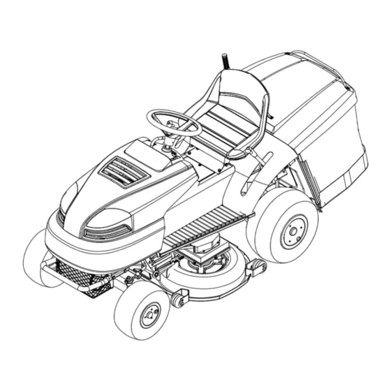
- Page 10 KNOW YOUR PRODUCT 10. (Cutting Height Adjusting) Lift Lever. This lever allows you to adjust the blade height to seven positions which range from 3cm – 9cm. 1. Gear Shift Lever. Changes the directional movement of the lawn tractor from reverse, neutral, 11.
- Page 11 KNOW YOUR PRODUCT Illustrated Drawings d e f Check Panel Lawn Tractor Rear Discharge...
- Page 12 KNOW YOUR PRODUCT Decals and Labels Lawn Tractor Rear Discharge...
-
Page 13: Slope Guide
SLOPE GUIDE Safe Mowing Guide SLOPE GUIDE ONLY RIDE UP OR DOWN A SLOPE NOT ACROSS ONLY RIDE UP OR DOWN A SLOPE NOT ACROSS 10° SLOPE MAXIMUM To prevent the serious injury, operate your lawn tractor °. WARNING: To prevent the serious injury, operate your lawn tractor up and down the slope, NEVER across the face. - Page 14 UNPACKING AND ASSEMBLY NOTE: Once you have moved the cutting deck to its maximum height, you can now roll your lawn tractor off the skid For storage and transport reasons, some components of the machine are not directly installed in the factory, but 1.
- Page 15 Assemble and checking the battery Fitting the steering wheel WARNING: Before installing the battery, 2. Position the front wheels of the lawn tractor so they are remove all metal bracelets, wrist watch pointing straight forward. (Fig 6) bands, rings and other metallic objects from your hands or other areas which may get in Fig 6 contact with the battery.
- Page 16 Fitting the seat 1. Lift the seat pan (3) into a Fig 9 vertical position. (Fig 9) 2. Place seat (1) onto the seat pan (3). 3. The underside of the seat has 4 threaded holes. Ensure that these threaded holes match the slots on the seat pan.
- Page 17 Tyre Pressure BEFORE STARTING 1. It is important to have the correct tyre pressure as it is Checks and Precautions the main condition for ensuring that the cutting deck is horizontal and thus mows evenly. 1. Do not use the machine for any other purpose other than the purpose of has been designed for (cutting and factory for shipping purposes.
- Page 18 Fuel Level Attaching the grass catcher WARNING: WARNING: IMPORTANT: The grass container is Fig 21 Fig 22 1. Tilt the grass catcher 2. Then lower the grass DANGER: RE-FUELLING SHOULD BE and then hook into catcher into position. CARRIED OUT IN AN OPEN WELL the slots.
- Page 19 Understanding your Controls OPERATION The following section will help you understand the how to Locatios of Controls operate the controls. IMPORTANT: Become familiar with the operation of controls before you start the lawn tractor. How to use the throttle control Always operate engine at full throttle.
- Page 20 How to use the shift lever To change the cutting height, raise or lower the lift lever as follows: To change the forward speed or the direction of the unit, 1. To release the lift lever, push the button on top of the follow the steps below.
- Page 21 How to stop the unit 1. Start the engine. Your tractor is equipped with an operator presence sensing 2. Move the lift lever to a height of cut position. switch. When engine is running, any attempt by the operator IMPORTANT: In high or thick grass, cut shut off the engine.
- Page 22 Before Starting the Engine conditions. If the engine is operated under the following Check the oil! NOTE: The engine was shipped from the factory WITHOUT instructions. oil. Check the level of the oil. Add oil as needed. 1. The engine has a loss of power or does not run smoothly.
- Page 23 Cold Starting WARNING: The pedal has to be 1. Transfer the gas control lever to the “START” position. released gradually as a sudden (Fig 29) engagement may cause tipping up and 2. Put the switch key into the switch box and turn it to the loss of control of the vehicle.
- Page 24 To start cutting 1. Connect each end of the RED “Jumper Cable” to the 1. Put the accelerator into the “FAST” position. positive (+) terminals of each battery. Make sure you do 2. Raise the cutting deck to its highest position. not touch the chassis with the cables.
- Page 25 How to obtain a good cut Keep the blade(s) sharpened. Worn blades will cause the ends of the grass to turn yellow. 1. If the grass is very tall, it should be cut twice in a Do not cut or bag grass that is wet. Wet grass will not discharge correctly.
- Page 26 Emptying the grass catcher container DANGER: NEVER GO DOWN THE HILL WITH THE TRAVEL LEVER IN THE NEUTRAL WARNING: Never let the grass catcher POSITION “N” – ALWAYS HAVE THE LAWN become too full as it may block the TRACTOR IN GEAR. collector channel.
- Page 27 6. Rinse the grass-catcher. 7. Then put the grass-catcher in a position where it can mowing, it is important to: 8. Store the lawn tractor away from harsh/wet weather cover with a cloth. position. the accelerator lever in the IMPORTANT: “SLOW”...
- Page 28 Lubrication Instructions MAINTENANCE The rating plate on your tool may show symbols. These represent important information about the product or Safety instructions on its use. F req uenc y C o m p o nents WARNING: Before you commence with cleaning, maintenance or repair work, General Purpose Grease, such as remove the ignition key and read the...
- Page 29 General Lubrication (25 hrs) Replacing the belt connecting blades Check all fastenings for Check the blade drive belt (25 hrs) Tension of transmission belts (25 hrs) Blade brake and engagement (10 hrs) Inspecting loose Replacing the blade (100 hrs) blade sharpness (25 hrs) Replacing the blade drive belt Replacement of...
- Page 30 Lawn tractor into a perpendicular position Battery In order to maximize the life of the battery it is essential The lawn tractor can be lifted into a perpendicular position to provide access to the lower part of the machine. purchase. IMPORTANT: It is recommended that a minimum of two competent people be of time.
- Page 31 Replacing the wheels Adjusting the mower cutting height Switch off the lawn tractor and elevate the frame by placing IMPORTANT: It is important to set the a load bearing part on the chassis which requires the wheel level of the mowing mechanism to to be changed.
- Page 32 Adjusting of the blade drive Replacing the drive belts The power output from the engine to the blades of the The lever which operates the engagement and mowing mechanism is transmitted by V-belt and disengagement of the blades also activates the operation gear-belt.
- Page 33 Adjusting the drive belt of the blades drive Adjusting the chain The tension of the belt can be adjusted with the adjustment 1. Check the chain tension after setting the drive nut as indicated in (Fig 49), by following these next steps: conversion unit to the highest gear.
- Page 34 WARNING: The blades facing each other WARNING: All operations on the blades at a right angle, and rotate against (dismantling, sharpening, balancing, themselves. When assembling keep the remounting and/or replacing) require a right position (Fig 54) certain familiarity and special tools. For safety reasons, go to a specialized centre if you do not have the right tools or experience.
- Page 35 TROUBLESHOOTING CAUSE PROBLEM CORRECTION Fill up your fuel tank. Tractor will not start Tractor is out of fuel. Engine is not “CHOKED” properly. See “TO START ENGINE” in Operation section. Wait several minutes before attempting to start. Spark plug is faulty. Replace the spark plug.
- Page 36 TROUBLESHOOTING CAUSE PROBLEM CORRECTION The tractor is losing Trying to cut too much grass/too fast. Raise cutting height/reduce speed. Throttle in “CHOKE” position. Adjust throttle control. power during The build-up of grass, leaves, dirt and Clean underside of mower housing. operation other trash under mower.
- Page 37 PARTS SCHEDULE Lawn Tractor Rear Discharge Lawn Tractor Rear Discharge...
- Page 38 PARTS SCHEDULE Lawn Tractor Rear Discharge...
- Page 39 PARTS SCHEDULE CONTENTS Lawn tractor Cutting deck Front axle Lifting level Hood Panel Electrical system Seat Bunker Gear shifting Lift segment Plate Decals DIFFERENCES OF THE T130,T140,T160,T180 Engine Segment Pin (R) Pin (L) Silencer Hose T130 009 919 P0093-01A P0100-00 P3836-00 P3838-00 PC3228-00...
- Page 40 PARTS SCHEDULE T130 T160 T140 T180 LAWN TRACTOR Lawn Tractor Rear Discharge...
- Page 41 PARTS SCHEDULE L A W N T R A C T O R Frame GC102-00-00 Cutting Deck P3580-00 Lever P0031-00 Lever P0032-00 Foot P3186 Screw M8 x 55 150B0855 ISO4017 (DIN933) 10 Washer 8.4 40208 ISO7093 (DIN9021) Nut M8 32808 ISO7040 (DIN982) 12 Bush 011 565...
- Page 42 PARTS SCHEDULE LAWN TRACTOR hoop 12 673B135 Washer Y0121 Channel P0253-00 Ring P0302 Screw M8x18 150B0818 ISO4017 (DIN933) Washer 8 40308 DIN127-B Ring P0306 Plate P0324 Nut M8 32808 ISO7040 (DIN982) Washer 8.4 40208 ISO7093 (DIN9021) 100a Washer 8 40308 DIN127-B Nut M10 32810...
- Page 43 PARTS SCHEDULE LAWN TRACTOR Quantity Splint pin 3.2x25 5003225 ISO1234 (DIN94) Nut M8 340B08 ISO4032 (DIN934) 153a Nut M8 ISO7040 (DIN982) 32808 153b Washer 9 ISO7089 (DIN125-A) 40108 Screw M8x20 150B0820 ISO4017 (DIN933) 203a Washer 8 40308 DIN127-B Strunt P0119 Holder P0186 Screw M8x20...
- Page 44 PARTS SCHEDULE T130 T160 T140 T180 LAWN TRACTOR Lawn Tractor Rear Discharge...
- Page 45 PARTS SCHEDULE LAWN TRACTOR Quantity Screw M5 × 25 150B0525 ISO4017 (DIN933) Washer 5.3 40205 ISO7093 (DIN9021) Nut M5 32805 ISO7040 (DIN982) Washer 9 40108 ISO7089 (DIN125-A) Engine 009 919 12.5HP Engine 009 916 13.5HP Engine 009 917 15.5HP Engine 009 918 17.5HP Screw M8 ×...
- Page 46 PARTS SCHEDULE LAWN TRACTOR Quantity 149 Washer 6.6 40106 ISO7089 (DIN125-A) 150 Nut M6 32806 ISO7040 (DIN982) Screw M6 × 16 150B0616 ISO4017 (DIN933) 152 Washer 6.4 40206 ISO7093 (DIN9021) 154 Key 012 070 156 Pulley P0767-00 156a Bush 121610 007 266 12*16*10 157 Shaft...
- Page 47 PARTS SCHEDULE LAWN TRACTOR Quantity Gear shifting P0864 309 Driver+Bush P0839-00 Holder P0862 Washer 5.5 40105 ISO7089 (DIN125-A) Washer 5 40305 DIN127-B Washer 8 40308 DIN127-B Pin B8 × 32 5100832 ISO2341(DIN EN22 341) Screw M8 × 20 150B0820 ISO4017 (DIN933) Screw M8 ×...
- Page 48 PARTS SCHEDULE LAWN TRACTOR Quantity 348 Washer 9 40108 ISO7089 (DIN125-A) 354 Bush 16 011 572 356 Lever P0382-00 358 Lever P3221-00 359 Pin 6 × 32 5280632 ISO8752 (DIN1481) 360 Spring 008 205 361 Draw.rod P0645-00 363 Nut M8 32808 ISO7040 (DIN982) 374 Spacer...
- Page 49 PARTS SCHEDULE T130 T160 LAWN TRACTOR Lawn Tractor Rear Discharge...
- Page 50 PARTS SCHEDULE T140 T180 LAWN TRACTOR Lawn Tractor Rear Discharge...
- Page 51 PARTS SCHEDULE LAWN TRACTOR Quantity Frame GC102-00-00 Front axle P3820-00 Front axle PA3820-00 P3161 Splint pin 4x45 5000445 ISO1234 (DIN94) P0093-01A PA0093-01A P0093-10-00 Washer 11 40110 ISO7089 (DIN125-A) Washer 10 40310 DIN127-B Nut M10*1 341B10 ISO8673 (DIN934) Nut M10*1.25 341C10 ISO8673 (DIN934) Buffer P3791...
- Page 52 PARTS SCHEDULE LAWN TRACTOR Quantity Splint pin 5x30 5000530 ISO1234 (DIN94) Steer.wheel E0041 Pin 6x55 5280655 ISO8752 (DIN1481) P0885 Screw M8x20 150B0820 ISO4017 (DIN933) Washer 9 40108 ISO7089 (DIN125-A) 202a Washer 8 40308 DIN127-B Yoke P0120 Washer 8 40308 DIN127-B 206a Washer 9 40108 ISO7089 (DIN125-A)
- Page 53 PARTS SCHEDULE T130 T160 T140 T180 LAWN TRACTOR Lawn Tractor Rear Discharge...
- Page 54 PARTS SCHEDULE LAWN TRACTOR Quantity Frame GC102-00-00 Holder P3567A Screw M6x16 150B0616 ISO4017 (DIN933) Hood P3561-00A Washer 6.4 40206 ISO7093 (DIN9021) Washer 6 40306 DIN127-B Screw M6x18 150B0618 ISO4017 (DIN933) Washer 6.4 40206 ISO7093 (DIN9021) Washer 6 40306 DIN127-B Nut M6 328B06 ISO10511 (DIN985) Pannel...
- Page 55 PARTS SCHEDULE LAWN TRACTOR Quantity Washer 9 40108 ISO7089 (DIN125-A) 282 Screw M8x55 150B0855 ISO4017 (DIN933) 285 Insert 92 813 Foot P3206 292 Washer 6.4 40206 ISO7093 (DIN9021) 292a Washer 6 40306 DIN127-B 293 Screw M6x16 150B0616 ISO4017 (DIN933) 294 Cover P3349-02 294a Screw M5x14 150B0514...
- Page 56 PARTS SCHEDULE T130 T160 T140 T180 CUTTING DECK Lawn Tractor Rear Discharge...
- Page 57 PARTS SCHEDULE CUTTING DECK Quantity Cutting deck P3580-00 Cover P3589-00 Plate P3168-00 Spindle P3587B Roller P0035-01 Pulley P3236 P0046 Shaft P3189 Shaft P3188 Driver P0087 Blade P0226 (D0226) Blade P0225 (D0225) Screw M10x1x25 151B1025 ISO8676 (DIN961) Screw P3220 Tightener P0081 ScrewM8*35 1920835 ISO8677 (DIN603)
- Page 58 PARTS SCHEDULE CUTTING DECK Quantity Spring 015 286 Bearing 6204-2RS 096 473 DIN625-T1 Bearing 6202-2RS 684 010 DIN625-T1 Circlip 35 43035 DIN472 Circlip 20 43120 DIN471 Circlip 15 43115 DIN471 Ring 9 43609 DIN6799 Screw P3585-00 Nut M8 32808 ISO7040 (DIN982) Screw M6x14 150B0614 ISO4017 (DIN933)
- Page 59 PARTS SCHEDULE CUTTING DECK Quantity Washer 10 40310 DIN127-B 99b Washer 10(Left) 403B10 DIN128-A Washer P0881 99d Washer P3236A Nut M6 32806 ISO7040 (DIN982) Washer 13.5 40112 ISO7089 (DIN125-A) Washer 6 40306 DIN127-B Washer 5.5 40105 ISO7089 (DIN125-A) Washer 5 40305 DIN127-B Holder...
- Page 60 PARTS SCHEDULE T130 T160 FRONT AXLE Lawn Tractor Rear Discharge...
- Page 61 PARTS SCHEDULE T140 T180 FRONT AXLE Lawn Tractor Rear Discharge...
- Page 62 PARTS SCHEDULE FRONT AXLE Quantity Front Axle P3820-00 Front Axle PA3820-00 Axle P3157-00 Bush 022 143 Head M10x1 280 145 Q700B10 Pin (R) P3836-00 Pin (R) PA3836-00 Washer =3.0 P3541A Washer =0.8 P3541 Pin (L) P3838-00 Pin (L) PA3838-00 Foot P0905 Screw M10*1.25x55 151C1055...
- Page 63 PARTS SCHEDULE T130 T160 T140 T180 LIFTING LEVER Lawn Tractor Rear Discharge...
- Page 64 PARTS SCHEDULE LIFTING LEVER Quantity Lifting Lever P0861 Tube P0549 Pawl P0166 Draw.rod P0237-00 Ratchet P0961 Spring 081 474 Bush P0523 Spacer P0525 Screw M6x35 150B0635 ISO4017 (DIN933) Washer 6 40306 DIN127-B Washer 6.4 40106 ISO7093 (DIN9021) Lever P0848-00 Lawn Tractor Rear Discharge...
- Page 65 PARTS SCHEDULE T130 T160 T140 T180 Lawn Tractor Rear Discharge...
- Page 66 PARTS SCHEDULE Quantity P0354 P0337-00 Bush 16 011 572 Draw.rod P0587 Spring 008 044 Suspension P0588 Spacer P0590 Screw 067 312 Nut M8 32808 ISO7040 (DIN982) Nut M12 32812 ISO7040 (DIN982) Washer 13.5 40112 ISO7089 (DIN125-A) Pin 6x25 5280625 ISO8752 (DIN1481) Washer 9 40108 ISO7089 (DIN125-A)
- Page 67 PARTS SCHEDULE T130 T160 T140 T180 REAR AXLE Lawn Tractor Rear Discharge...
- Page 68 PARTS SCHEDULE REAR AXLE Quantity Rear axle P0885 P0895 Wheel P0125 Satelits P0128-00 Wheel P0126 Cover P0112 Washer P0266 Shaft P0278 Shaft P0279 Axle P0178-00 Bearing 6204-2RS 096 472 Bearing 6004-2RS 477 942 Circlip 47 43047 DIN472 Circlip 42 43042 DIN472 Screw M6x20 150B0620...
- Page 69 PARTS SCHEDULE T130 T160 T140 T180 REAR AXLE Lawn Tractor Rear Discharge...
- Page 70 PARTS SCHEDULE REAR AXLE Quantity Rear axle P0885 P0895 Washer P0887 Collar 108 766 Pinion P0124 Spacer P0779 Wheel P0891 Wheel P0121 Wheel P0889 Bush 006 453 Ring 016 833 P0453 Ring 016 876 Washer P0267 Box-angle plate P0844 N0701 Coupling P0893 Fork...
- Page 71 PARTS SCHEDULE REAR AXLE Quantity P0216 P0413 P3201 P0411 Sprocket P0240 47a Bush (12*17*12) 006 586 12*17*12 P0243 Spacer P0221 Sprocket P0153 Circlip 32 43032 DIN472 Lamella P0160 Washer 11 40110 ISO7089 (DIN125-A) 53a Washer 019 364B 53b Washer 019 364C 53c Washer 019 371B Tichtener...
- Page 72 PARTS SCHEDULE REAR AXLE Quantity Nut M10 33210 ISO7042 (DIN6925) Washer 10 40310 DIN127-B Nut M8 33208 ISO7042 (DIN6925) Nut M12x1.25 351B12 ISO8675 (DIN439) Chain 92 834 06B--1*84 Bearing 6205-2RS 089 931 25*52*15 Bearing 6005-2RS 620 012 25*47*12 Circlip 10 43110 DIN471 Nut M10...
- Page 73 PARTS SCHEDULE T130 T160 T140 T180 HOOD Lawn Tractor Rear Discharge...
- Page 74 PARTS SCHEDULE HOOD Quantity Hood P3561-00A Hood P3561A Headlamp (L) 021 806B Headlamp seat (L) 647 081B Headlamp cover (L) 013 373B Headlamp (R) 021 806C Headlamp seat (R) 647 081C Headlamp cover (R) 013 373C Vent upside P3562A-02 Sponge N2003 Screw ST8*19 2710819...
- Page 75 PARTS SCHEDULE T130 T160 T140 T180 PANEL Lawn Tractor Rear Discharge...
- Page 76 PARTS SCHEDULE PANEL Quantity Panel P3288 Panel GC102-A-09-01B Reinforce P3356A-00 Operating device P0593-00 Screw M5x16 150B0516 ISO4017 (DIN933) Stay wire P0907-00 Nut M5 32805 ISO7040 (DIN982) Plugboard underprop P3356H Washer 5.5 40105 ISO7089 (DIN125-A) Washer 5 40305 DIN127-B Screw M3x10 2140310 ISO7045 (DIN7985) Washer 3.2...
- Page 77 PARTS SCHEDULE T130 T160 T140 T180 ELECTRICAL SYSTEM Lawn Tractor Rear Discharge...
- Page 78 PARTS SCHEDULE T130 T160 T140 T180 ELECTRICAL SYSTEM Lawn Tractor Rear Discharge...
- Page 79 PARTS SCHEDULE ELECTRICAL SYSTEM Quantity Electrical system P0486 Accumulator 007 343 Rubber inlet N2005 El.conductor P0167 El.conductor P0487 El.conductor P0488 Switch 007 840 Switch 007 385 Bundle 13/102.48.100 Strap 67405100 Fuse 007 771 Relay 007 630 Screw M6x16 150B0616 ISO4017 (DIN933) Washer 6.6 40106 ISO7089 (DIN125-A)
- Page 80 PARTS SCHEDULE T130 T160 T140 T180 SEAT Lawn Tractor Rear Discharge...
- Page 81 PARTS SCHEDULE SEAT Quantity Seat P0975 Seat(soft) 019 532A Plate E0021 Spacer Y0414 Spring slice N1273 Screw M8x20 150B0820 ISO4017 (DIN933) Nut M8 32808 ISO7040 (DIN982) Washer 9 40108 ISO7089 (DIN125-A) Washer 5.3 40205 ISO7093 (DIN9021) Washer 5 40305 DIN127-B Nut M5 32805 ISO7040 (DIN982)
- Page 82 PARTS SCHEDULE T130 T160 T140 T180 BUNKER Lawn Tractor Rear Discharge...
- Page 83 PARTS SCHEDULE BUNKER Quantity Bunker P3101 Grassbag 015 356-00 Cover 012 364 Grip P3104 Overturn pole P0880 Grip P0923 High section P3103-00 Skew pole P0140 Low section P0137 Frame P0935 contacter N3401 Screw M5x30 150B0530 ISO4017 (DIN933) Washer 5.5 40105 ISO7089 (DIN125-A) Nut M5 32805...
- Page 84 PARTS SCHEDULE T130 T160 T140 T180 GEAR SHIFTING Lawn Tractor Rear Discharge...
- Page 85 PARTS SCHEDULE GEAR SHIFTING Quantity Gear shifting P0864-00 Tube P0849 Segment P0855 Bush P0523 Bush P0524 Insert P0843 Ring P0522 Roller 4x14B 5220414 ISO2338 (DIN7) Washer 6.6 40106 ISO7089 (DIN125-A) Spring 645 455 Lawn Tractor Rear Discharge...
- Page 86 PARTS SCHEDULE T130 T160 T140 T180 SEGMENT Lawn Tractor Rear Discharge...
- Page 87 PARTS SCHEDULE SEGMENT Quantity Lift segment P0774 Lift segment P0357A-00 Rope P0775A-00 Lawn Tractor Rear Discharge...
- Page 88 PARTS SCHEDULE T130 T160 T140 T180 PLATE Lawn Tractor Rear Discharge...
- Page 89 PARTS SCHEDULE PLATE Quantity Plate P0324 Screw M6x16 1840616 ISO4162 (DIN6921) Lock Pawl GC102-100 Spring GC102-101 Draw.rod P0645-00 Nut M8 340B08 ISO4032 (DIN934) Screw M10x25 150B1025 ISO4017 (DIN933) Plate GC102-90-00 Screw M6x14 150B0614 ISO4017 (DIN933) Washer 6 40306 DIN127-B Washer 6.4 40206 ISO7093 (DIN9021) Washer 10.5...
- Page 90 PARTS SCHEDULE T130 T160 T140 T180 DECALS Lawn Tractor Rear Discharge...
- Page 91 PARTS SCHEDULE DECALS Quantity Decals P3350-00 Decal, Dashboard display P3349-01K Decal, Operating instruction P3349-01 Decal, Safety P3349-01D Decal, Danger of cutting P3349-01F Decal, Danger of hot P3349-01M Decal, Blade engagement P3349-01H Decal, Light switch P3349-01P Decal, Key ignition switch P3349-01E Decal, Gas control lever P3349-01G Decal, Parking brake button...
- Page 92 PARTS SCHEDULE INDEX ORDERING NUMBER NUMBER OF GROUP NUMBER OF CATALOGUE ITEM 32805 33208 40108 153b 32805 33208 40108 32805 33210 40108 32805 38010 40108 32805 40103 40108 32806 40103 40108 32806 40104 40108 32806 40104 40108 32806 40105 40108 206a 32806 40105...
- Page 93 PARTS SCHEDULE INDEX ORDERING NUMBER NUMBER OF GROUP NUMBER OF CATALOGUE ITEM 40306 40310 5003218 40306 40310 5003225 40306 40310 5100832 40306 40312 182a 5210832 40306 40312 5220414 40306 40408 5280430 40306 43032 5280625 40306 43035 5280625 40306 43042 5280632 40306 43047 5280635...
- Page 94 PARTS SCHEDULE INDEX ORDERING NUMBER NUMBER OF GROUP NUMBER OF CATALOGUE ITEM 150B0820 340B06 F0003-00 150B0820 340B08 F0004 150B0820 340B08 F0005 150B0820 340B08 F0006-00 150B0820 340B08 GC102-00-00 150B0820 340B10 GC102-00-00 150B0820 340B10 GC102-00-00 150B0820 340B10 GC102-00-07 150B0820 340B10 GC102-100 150B0820 341B10 GC102-101 150B0822...
- Page 95 PARTS SCHEDULE INDEX ORDERING NUMBER NUMBER OF GROUP NUMBER OF CATALOGUE ITEM P0211 P0481-00 P0848-00 P0216 P0486 P0849 P0220 P0487 P0852 P0221 P0488 P0855 P0225(D0225) P0522 P0861 P0226(D0226) P0523 P0861 P0227 P0523 P0862 P0237-00 P0524 P0864-00 P0240 P0525 P0864-00 P0243 P0549 P0876 P0253-00...
- Page 96 Machines Gadgets and Gizmows Ltd Postal address: PO Box 592, Kerikeri 0245, New Zealand. Warehouse & Offices: 7-9 General Gates Avenue, Kerikeri 0230, New Zealand. Phone: (+64) Ø9 401 6360. Fax (+64) Ø9 401 6350. Email: info@MGG.co.nz Website www.MGG.co.nz...
Need help?
Do you have a question about the Gizmow T130 and is the answer not in the manual?
Questions and answers
Gdzie szukać części do traktora mgg gizmow 160t. Pozdrawiam
Parts for the MGG Gizmow T130 tractor can be found through Machines Gadgets and Gizmows Ltd. Their warehouse and offices are located at 7-9 General Gates Avenue, Kerikeri 0230, New Zealand.
This answer is automatically generated
@Mr. Anderson Parts now available by emailing t180mowers@protonmail.com Please quote manual page number and part number when ordering