Table of Contents
Advertisement
Quick Links
Advertisement
Table of Contents

Summary of Contents for Rockwell Automation CDN366
- Page 1 CDN366 DeviceNet Gateway Application Notes...
-
Page 2: Table Of Contents
Table of Contents Revision........................... 3 Purpose:........................... 4 Hardware and Software Requirements:................4 Schematic Diagrams:....................... 5 CDN366 Setup & Configurations: .................. 7 Register Electronic Data Sheet (EDS) File: ..............8 CDN366 Parameter Configuration:................13 Change Parameter Setting Using RSNetWorx:............. 16 Serial Stream Object Parameters (Class Code 64):............ -
Page 3: Revision
Revision Initial Release ……………………………………………………………..……. 6/12/01... -
Page 4: Purpose
Based on application requirements, the CDN366 can integrate with many brands of PLC (AB, Omron, etc.) or PC based platforms (Synergetic, etc.). As long as a DeviceNet network is available for a particular application, the CDN366 should be able to integrate in the network. -
Page 5: Schematic Diagrams
Schematic Diagrams: The electrical schematic diagram figure 1 shown on page 3, CDN366 is integrated with an Allen Bradley (AB) SLC502. The AB SLC500 four-slot rack system contains a rack power supply (1747-P1), a PLC processor on slot 0 (1747-L524), and a DeviceNet scanner module on slot 1 (1747-SDN), an 8 points input module on slot 2 (1746-IV8), and an 8 points output module on slot 3 (1747-OB8). - Page 6 RS232 Pin Layout DeviceNet DeviceNet Connector Male Connector Func. Func. Color Description clear shield (Drain) V+ (BUS+) black V- (BUS-) Pin 1,4,6,9 are unused white data high (CAN H) blue data low (CAN L) Figure 1. CDN366 Integrate with Allen Bradley SLC500...
-
Page 7: Cdn366 Setup & Configurations
CDN366 Setup & Configurations: Prior to the setup and configuration of the CDN366 device, the PLC hardware (power supply, CPU, DeviceNet scanner, I/O modules), software (RSLinx, RSNetWorx & RSLogic500) and interface modules must be setup and configured first. (For further information on setup and configuration of the Allen Bradley PLC controller, please visit www.ab.com) -
Page 8: Register Electronic Data Sheet (Eds) File
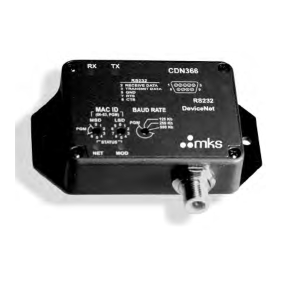
Set the DeviceNet baud rate to match with the network baud rate. Set the Mac ID to an unused node address. The example below shows that the CDN366 was set at Mac ID 01 (MSD=0, LSD=1), and DeviceNet network baud rate is at 125Kb. - Page 9 In order to register the CDN366 on RSNetWorx, click on “Tools” and select “EDS Wizard”. Click on “Next>” and the “Options” menu is prompted. Select “Register an EDS file(s)” and click on “Next>”...
- Page 10 Select “Register a single file” and enter the EDS file name on the white box. Click on “Next>”...
- Page 11 The “EDS File Installation Test Results” menu is prompted, click on “Next>”. The “Change Graphic Image” menu is prompted. Select CDN366 and click on “Change icon”. Select another icon to replace current CDN366 icon. Click “OK” to exit “Change Icon” menu. After it is changed to a new icon, click on “Next>”.
- Page 12 The “Completing the EDS Wizard” menu is prompted. Click on “Finish” to complete the EDS Wizard. On RSLinx and RSNetWorx, click on the “Online” icon to re-scan or browse the network. The CDN366 should be identified on the RSLinx and RSNetWorx network.
-
Page 13: Cdn366 Parameter Configuration
Now, the CDN366 is on the DeviceNet network. To change the CDN366 parameters, ensure that the CDN366 device is not on the DeviceNet master scanlist. To edit the parameters on CDN366, point the mouse to CDN366 icon and right click. - Page 14 When the sub-menu is prompted, click on “Properties” and the “CDN366” menu appears. Select “Parameters”, and the “EDS Editor” sub-menu is prompted. Click on “Upload”, and the default parameters will upload from CDN366 device.
- Page 15 Restore default parameters Monitor Parameters The CDN366 has eight (8) Rx/Tx instances. The total number of parameters are 155. On the “Groups” selection, click on the “down arrow key” and then select “Serial Stream Object”, “Rx Inst 1” or “Tx Inst 1”.
-
Page 16: Change Parameter Setting Using Rsnetworx
Change Parameter Setting Using RSNetWorx: The CDN366 must be offline (not on Scanlist) to change any parameters. Some of the parameters cannot be change, but can be read (see CDN366 DeviceNet Specifications for details). Before making the parameter change, always upload the current parameters from the CDN366 device. -
Page 17: Serial Stream Object Parameters (Class Code 64)
5) Flow Control: The flow control can be set at 0, 1, or 2. When flow control is set to 1, the X-Off (CTRL S) will force the CDN366’s transmit function to block. The transmitted characters are stored in the FIFO buffer until transmission is re- enable by sending the X-On (CTRL Q) character to the CDN366. - Page 18 (short string data type range 1~256 bytes) that trigger CDN366 to read the beginning of a data packet. Post-delimiter is a character or list of characters (short string data type range 1~256 bytes) that trigger CDN366 to read the end of a data packet.
- Page 19 Length – When a value (byte range from 1~255) is set in the Packet Length, (Class=64, Instance=1, Attribute=14) the data packet is fixed based upon the Packet Length. As the data packet receives from a poll response, the data packet is complete as number of bytes sent is equal to the byte value set in Packet Length.
-
Page 20: Serial Receive Object Parameters (Class Code 65)
Serial Receive Object Parameters (Class Code 65): There are eight identical receive (Rx) instance parameters which can be set in CDN366. This section will review one of the eight receive instance parameters. These parameters can easily be changed using RSNetWorx. When using RSNetWorx to upload the parameters, first go to “Groups”... - Page 21 17) Data In Poll Response: When data in the poll response is set to 1 (enable), the Receive Data packet (bytes) of a particular instance is added in the CDN366’s Poll Response. Any particular Rx instances, which are unused, must be disabled.
-
Page 22: Serial Transmit Object Parameters (Class Code 66)
Data Type. This attribute should be disabled for all unused instances. 19) Sync Enabled: When sync enable is set to 1, the CDN366 will not respond with new serial data until the value in the Receive Acknowledge bit has been toggled. - Page 23 22) Transmit Mode: (class=66, instance=1, attribute=6) Bits 5~7 are unused. The transmit mode is used for transmitting the data in conjunction with strings before and/or after data. The String1 (class=66, instance=1, attribute=7) is a list of ASCII characters (bytes) to be transmitted. The String2 (class=66, instance=1, attribute=8) is a list of ASCII characters (bytes) to be transmitted.
- Page 24 Decimal Hex. Data Type Date Size (byte) Value Range 0xC2 SINT (signed 8-bit integer) -128 ~ 127 0xC3 INT (signed 16-bit integer) -32768 ~ 32767 0xC6 USINT (unsigned 8-bit integer) 0 ~ 255 0xC7 UINT (unsigned 16-bit integer) 0 ~ 65535 0xCA REAL (32-bit floating point value) +1.175E-38 ~ +3.4028E+38...
-
Page 25: Serial Receive/Transmit & I/O Mapping
300 bytes for each input and output I/O mapping. The serial data sent or received by the CDN366 cannot be viewed on the M-file. M- file does not exist in data memory table. The serial data in the M-file must be copied to a N integer file in order to be able to view the data. - Page 26 I:1.2, bits 0~7. The ASCII characters (bytes) data received by the CDN366 are mapped onto words I:1.2 ~ I:1.31 (depending on the data size.) Each ASCII character is equivalent to one byte. Two bytes are equivalent to one word.
-
Page 27: Transmit Handshaking & I/O Mapping
allocated for three characters (bytes) for serial receive. The total is ten bytes for PLC I/O mapping. Input Memory Table of Allen Bradley 1747-SDN DeviceNet Master Scanner Module Data 1 Word Addressing I/O 1 byte = 8 bits 1 byte = 8 bits Memory Table I:1.0... - Page 28 When data is sent from PLC to the RS232 serial connection, the Input I:1.1 bit 0 (Instance 1) toggles when the data is transmitted by the CDN366. Bit 0 toggles between 0 and 1. Instances 2~8 are setup similarly mapped to bits 1~7.
- Page 29 Example: The table below shows a short string data type with two transmit instances that are mapped into discrete/M-file Outputs I/O. Each instance is allocated for three characters (bytes) for serial transmit. The total is ten bytes for the PLC I/O mapping.
-
Page 30: Mapping The Poll I/O Connection To Ab-1747-Sdn
4 bytes to include the length byte. Example: Using RSNetWorx for DeviceNet to map CDN366 for receiving 14 bytes of barcode data and transmitting 1 byte for data confirmation. Typical in many applications, CDN366 is setup to use only one instance. - Page 31 6) If the “EDS Editor” menu is not prompted then click on the “Upload” icon to upload the latest parameters to the CDN366. 7) Click on “All Parameters” and select “Rx Inst 1”. 8) Click on “(Rx Inst-1) Data Size” and enter 15.
- Page 32 The 17 and 4 bytes are needed to map to 1747-SDN module. 20) In RSNetWorx, right click on the CDN366 icon. 21) Double click on “Properties” 22) The “1747-SDN Scanner Module” menu is prompted.
- Page 33 25) Move the CDN366 from the box “Available Devices” to the box “Scanlist”. 26) Click on “Edit I/O Parameters” 27) The byte values from “Poll Produce Size” and “Poll Consume Size” are 17 and 4. 28) Enter 17 on box Rx Size (bytes).
- Page 34 32) After selecting Automap, the discrete Input/Output tables should look the same as above. 33) The Advance I/O Mapping shows current mapping configurations. The memory Map To is Discrete (not M-file, based on user preference/applications). The data map starts in the memory register of Word 1, Bit 0. The Output Bit Length is 32 (equivalent to 4 bytes), and the Input Bit Length is 136 (equivalent 17 bytes).
-
Page 35: Basic Troubleshooting
Basic Troubleshooting Problem Could be caused by 1) DeviceNet master scanner did not recognize the 1) EDS file is not registered. device. 2) DeviceNet master scanner did not recognize the 2) Device minor and major revisions do not match device after loading the EDS file. EDS file. -
Page 36: Ascii Table
ASCII Table Non-Printing Characters Printing Characters Ctrl Name Dec Hex Char Dec Hex Char Dec Hex Char Dec Hex Char char ctrl- 00 NUL 20 Space null ctrl- 01 SOH start of heading 02 STX " start of text ctrl- 03 ETX end of text ctrl-... - Page 37 ctrl- 19 EM end of medium 26 1A SUB 58 3A 90 5A 122 7A substitute ctrl- 1B ESC escape ctrl- 1C FS 60 3C < 92 5C 124 7C file separator ctrl- 29 1D GS 61 3D 93 5D 125 7D group separator ctrl-...
-
Page 38: Cdn366 Enclosure Dimensions
CDN366 Enclosure Dimensions 1.25 0.65 0.45 3.80 4.30 3.30 0.50 0.12 Mtg. Holes 1.225 (2) 0.19 DIA. 1.225 0.725 0.625 DIA. On Case Wall 0.70 0.542 1.10... -
Page 39: Cdn366 Template
CDN366 Template Class Instance Attribute Default Setting Unit Comments... - Page 40 Allen-Bradley Home Page Welcome to our site! Web Tools Search Register to become an A-B Internet Member Contact Us Modify User Profile Reset Password Resources * Product Directory * Product Directory Find a Local Distributor Shop On-Line MCC W ETHOD IRING IAGRAMS Events Listing...
- Page 41 Allen-Bradley Home Page Copyright © 2002, Rockwell Automation. All rights reserved. Important Notices http://www.ab.com/ (2 of 2) [2/19/2002 1:24:08 PM]...
- Page 42 Manuals On-line -- I/O Library I/O Library System Requirements Web Tools · · · 1734, 1734D POINT I/O 1790, 1790D Compact Block LDX 1794 FLEX I/O Modules Search · · · 1746/1747 I/O Modules 1791 Block I/O 1797 FLEX Ex Modules Register to become an ·...
- Page 43 Manuals On-line -- I/O Library High Density Analog Input Modules 1746-NI8, -NI16I, -NI16V Product Profile Nov 1999 1746-PP001A-US-P for Demanding Process Control Applications SLC 500 Analog Input Modules 1746-NI16I, 1746-NI16V User Manual Dec 1999 1746-UM001A-US-P Installation Instructions Dec 1999 1746-IN001B-US-P SLC 500 RTD/Resistance Input 1746-NR4 and 1746-NR8 Technical Data...
- Page 44 Manuals On-line -- I/O Library SLC500 32-Point I/O Modules 1746-IB32, -IV32, -OB32, and -OV32 Installation Instructions Dec 1998 1746-5.19 Communication Modules Product/Title Catalog Number Publication Type Date Publication Number 1746-BAS Module Floating Point 1746-BAS Release Notes Sep 1999 1746-DU001A-US-P Conversion SLC500 BASIC and BASIC-T 1746-BAS and 1746-BAS-T Installation Instructions Mar 2000...
- Page 45 Data Table Access Module May 1993 1747-903 (Operator's Reference) Program Storage Device 1747-PSD Document Update Sep 2001 1747-DU003B-EN-P Installation Instructions Nov 2001 1747-IN001B-EN-P Copyright © 2002, Rockwell Automation. All rights reserved. Important Notices http://www.ab.com/manuals/io/1746/index.html (4 of 4) [2/19/2002 1:28:19 PM]...
-
Page 46: Installation Instructions
Installation Instructions (Catalog Number 1770-KFD and 1770-KFDG) The 1770-KFD module is a portable RS-232 communication interface that provides a host computer access to a DeviceNet network. This document contains this information: New or modified information is highlighted by a revision bar. - Page 47 DeviceNet RS-232 Interface Module Purpose Use this document to learn how to install and use the DeviceNet RS-232 interface module. Audience Read this manual before you install or use the DeviceNet RS-232 interface module. You should be familiar with DeviceNet technology. Precautionary Statements ATTENTION: Important:...
- Page 48 DeviceNet RS-232 Interface Module European Union Directive Compliance This product has the CE mark and is approved for installation within the European Union and EEA regions. It has been designed and tested to meet the following directives. EMC Directive: This apparatus is tested to meet Council Directive 89/336/EEC Electromagnetic Compatibility (EMC) using a technical construction file and the following standards, in whole or in part: EN 50081-2...
-
Page 49: Related Publications
DeviceNet RS-232 Interface Module Handling the Module ATTENTION: This RS-232 module uses CMOS technology, which is highly sensitive to electrostatic discharge (ESD). ESD may be present whenever you are handling the module. Take these precautions to guard against electrostatic damage: Avoid touching the interface connector pins on the RS-232 module. - Page 50 DeviceNet RS-232 Interface Module With this package you should receive: one DeviceNet RS-232 interface module, catalog no. 1770-KFD one 1770-KFD driver diskette two DIN rail mounting brackets four DIN rail mounting bracket screws one 6 ft, 9-pin D-shell RS-232 null-modem cable one unsealed DeviceNet terminal connector one copy of publication 1770-5.6, DeviceNet RS-232 Interface Module Installation Instructions...
- Page 51 DeviceNet RS-232 Interface Module Available options: global 9V ac power supply adapter (90 – 260V ac), which comes with catalog no. 1770KFDG/A domestic 9V ac power supply adapter (120V ac), which you can order separately as catalog no. 1787USADPTR/A Each adapter connects to the power supply connector on the 1770-KFD module. See page for additional information.
- Page 52 DeviceNet RS-232 Interface Module an 8 ft, 5-pin DeviceNet unsealed probe cable (catalog no. 1787-PCABL), which you can order separately a 6 ft, sealed T-tap DeviceNet connector cable (catalog no. 1787-TCABL), which you can order separately This cable connection lets the 1770-KFD module and a device connected to the module in a point-to-point configuration draw power from the network.
- Page 53 DeviceNet RS-232 Interface Module The 1770-KFD module, described in Figure 1, is a portable RS-232 communication interface that provides a host computer access to a DeviceNet network.
- Page 54 DeviceNet RS-232 Interface Module The 1770-KFD module lets you communicate: point-to-point (host computer directly to device via the 1770-KFD module) The host computer uses a point-to-point connection for node and/or parameter configuration. via a DeviceNet network connection...
- Page 55 DeviceNet RS-232 Interface Module The 1770-KFD module performs data transmission, management, and local network diagnostics. Allen-Bradley DeviceNet Manager software, 1787-MGR, manages data transmission and reception through the 1770-KFD interface module from a personal computer (Windows operating system). You can mount the module on a DIN rail. 1.
- Page 56 DeviceNet RS-232 Interface Module 2. Snap the mounting brackets onto the DIN rail.
- Page 57 DeviceNet RS-232 Interface Module The 1770-KFD module can be powered from either an external power supply or from a DeviceNet network. Supplying Power via AC Wall Adapter Figure 2 shows the power supply, catalog no. 1787-USADPTR, that takes 120V ac and outputs 9V dc at 1 amp. Figure 3 shows the global power supply, which takes 90 –...
- Page 58 DeviceNet RS-232 Interface Module Important: You must supply the cable between the adapter and the outlet. Supplying Power via Network The DeviceNet network can power the 1770-KFD module. Important: When the module is connected to a powered DeviceNet network, the network connection overrides the external power supply. Supplying Power to a Device The module can supply power to a device in a point-to-point connection.
- Page 59 DeviceNet RS-232 Interface Module Use the wiring key molded on the bottom of the 1770-KFD module when connecting the RS-232 cable to a computer. Use these wiring configurations:...
- Page 60 DeviceNet RS-232 Interface Module RS-232 Cable Connections (via 9-pin serial port connector) These pin numbers correspond with these connections: Connect the 1770-KFD module to a computer by using the RS-232 cable.
- Page 61 DeviceNet RS-232 Interface Module Using the Interface Module with a Portable Computer Some portable computers have power-saving modes that power down the serial ports during inactive periods, occurring most often when batteries power the PC. The serial-port power-saving feature causes the RS-232 interface module to go offline and to cease communication with DeviceNet Manager.
- Page 62 DeviceNet RS-232 Interface Module Follow these steps to connect the 1770-KFD module to a DeviceNet network: 1. Connect the DeviceNet cable (trunkline or dropline) to the unsealed DeviceNet terminal connector. 2. Connect the terminal connector to the 1770-KFD module. Important: DeviceNet cable connections should match color bars/electrical diagram on top of 1770-KFD module.
- Page 63 DeviceNet RS-232 Interface Module Connecting the 1770-KFD Module to DeviceNet Devices (Point-to-Point) You can connect the module to a sealed or an unsealed device in a point-to-point configuration. Connect to an unsealed device in one of two ways: use a 1787-PCABL probe cable use DeviceNet drop or trunk cable...
- Page 64 DeviceNet RS-232 Interface Module Connect to a sealed device in one of three ways: use a 1787-TCABL T-tap cable (and power supply) use a 1787-TCABL T-tap cable (and draw power from the network)
- Page 65 DeviceNet RS-232 Interface Module use a 1787-MCABL unsealed drop cable (and power supply) Probing a Network You can probe a sealed or an unsealed network with the 1770-KFD module. Probe an unsealed network in one of two ways: use a 1787-PCABL probe cable...
- Page 66 DeviceNet RS-232 Interface Module use a DeviceNet terminal connector Probe a sealed network in this way: use a 1787-MCABL unsealed drop cable...
- Page 67 DeviceNet RS-232 Interface Module If you are using a WinDNet -compatible application, you must install the 1770-KFD driver. Follow these steps: 1. Start Windows 3.1, Windows 95, or Windows NT. 2. Select Run from the File menu. 3. On the command line, type a:\setup as shown here: 4.
- Page 68 DeviceNet RS-232 Interface Module The three status indicators on the module give you information about your network and its connections. Figure 4 identifies each status indicator. The tables on page outline the indicator condition and the corresponding status, and explain what each condition means to you.
- Page 69 DeviceNet RS-232 Interface Module Module Status Indicator Network Status Indicator RS-232 Status Indicator...
- Page 70 DeviceNet RS-232 Interface Module...
- Page 71 DeviceNet RS-232 Interface Module At Allen-Bradley, customer service means experienced representatives at Customer Support Centers in key cities throughout the world for sales, service, and support. Our value-added services include: Technical Support SupportPlus programs telephone support and 24-hour emergency hotline software and documentation updates technical subscription services Engineering and Field Services...
- Page 72 DeviceNet RS-232 Interface Module...
- Page 73 DeviceNet is a trademark of the Open Device Vendors Association (ODVA). WinDNet and PLC-5 are trademarks of Allen-Bradley Company, Inc. Windows and Windows NT are trademarks of Microsoft.
Need help?
Do you have a question about the CDN366 and is the answer not in the manual?
Questions and answers