
Related Manuals for wanscam M-Jpeg Series


Summary of Contents for wanscam M-Jpeg Series
-
Page 1: User Manual
Wireless/Wired Network IP Camera For PC View) Night Vision & Remote Operation User Manual... -
Page 2: Packing List
Thank you for buying our IP camera Wanscam M-Jpeg Series IP Camera products are designed and equipped for local and remote network video surveillance system, including wired IP bullet camera, wireless IP bullet camera, IP IR dome camera, IP IR waterproof camera, IP Pan/Tilt/Zoom Camera etc. -
Page 3: Table Of Contents
Table of CONTENTS 1. Product Introduction ...................3 1.1. Safety Introduction ..................3 1.2. Product Specifications..................3 1.3. System Requirements..................3 1.4. Product Views……………..........…………....4 1.4.1 Front View......................4 1.4.2 Interface View....................5 1.5. Hardware Installation..................5 1.6. Software Installation..................6 2. Software Operation....................6 2.1. Search Tool Software..................6 2.1.1. -
Page 4: Product Introduction
1. Product Introduction 1.1 Safety Instructions (1). Use the proper power source. Do not use this product with a power source that supplies more than the specified Voltage (100-240V AC). (2). Never insert anything metallic into the camera. Inserting metal object into the camera can be a source of dangerous electric shock. (3). -
Page 5: System Requirements
Server function; *- Built in Web Server, convenient for users to use standard browse to realize the real time monitoring and setting administration; *-Support WIFI:802.11 b/g/n wireless networking; *-Support remote system update; *-Support DDNS analysis, support LAN & Internet (ADSL,Cable Modem) *-Support variety of network protocol: TCP/IP, UDP, SMTP, PPPoE, Dynamic DNS, DNS Client, SNTP, BOOTP, DHCP, FTP, SNMP, WIFI/802. -
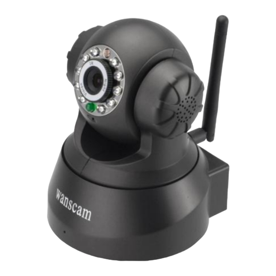
Page 6: Product Views
1.4. Product Views 1.4.1 Front View 1.4.2 Interface View Figure 1.1 Figure 1.2 1: Audio Out , 2: Audio In 3: Ethernet interface: RJ-45 interface. Power Supply Light: constant on after power up Network light: constant sparkle after power up data transmission. 4: Antenna: 5: Power input interface: connect direct current 5V Power TF Socket : No use for this model. -
Page 7: Software Installation
1.6 Software Installation Figure 1.4 Open the CD Install the follow software: 1. ActiveX: Click “OCX setup”—“Next”—“Install”—“Finish”. 2. Search Tool: Open the CD, click ,The Search Tool will run automatically.( No need to install. You can copy this software to your desktop.) Figure 1.5 2. -
Page 8: Configuration Of The Network
Figure 2.1 Note: The software searches IP Servers automatically over LAN. There are 2 cases: 1. No IP Cameras found within LAN. After about 1 minute search, the Equipments List Field not show the IP address. 2. IP Cameras have been installed within LAN. All the IP Cameras will be listed and the total number is displayed in the Equipments list field as shown in Figure 2.1 Note:... -
Page 9: Real-Time Video Demonstration
IP address: Fill in the IP address assigned and make sure it is in the same subnet as the Gateway, and the subnet should be the same as your computer or router. (i.e. the first three sections are the same) Subnet Mask: The default subnet mask of the equipment is: 255.255.255.0. -
Page 10: View Via Ie Browser
Figure 3.2 (1) ActiveX Mode (For IE Browser): available in IE6.0 or above explorer (2) “RTSP Stream Mode”: available in Firefox, Safari, and Google browser. (3) “No Plug-In Mode”: available in smart phone browser. (4) SD card video playback online 3.2. - Page 11 Figure 3.3 After Download Ocx-Setup (oPlayer Software), Click and install it, untill finished. Figure 3.4...
- Page 12 Figure 3.3 Windows XP system Figure 3.4 Win7 System Note: If there is still no live video after run ActiveX, please try to enable the ActiveX options of IE security settings, please do the follow steps: 1. Close the firewall of your computer. 2.
- Page 13 Figure 3.6 In Addition: you can also click “start” menu->“Internet Explorer”, choose “Internet attributes “ to enter, or via “Control Panel” ->“Internet Explorer”, enter to Security setting. 3. If there is still no image, please close your anti-virus software, and then try step 1 & 2 again.
-
Page 14: View Via Safari, Firefox, Google Browser
NOTE: Make sure that the firewall or anti-virus software doesn’t block the software or ActiveX. If you couldn’t see live video, please close your firewall or anti-virus software, and try again. 3.3. View via Safari, Firefox, Google Browser Choose Server Push Mode (For Safari, Firefox, Google Browser), and sign in Server Push Mode doesn’t support ActiveX, so some functions are not available, such As Record, Audio, Talk, Speaker,The speed control bar, Zoom etc.),if you want to use these functions, please use IE Browser. - Page 15 Figure 3.8 The Pan/Tilt Feature only work when the cameras have this Pan/Tilt function. This option enables log detection. After the online user clicks this button, a log is entered into the camera’s Log Data documenting the IP address of users who have accessed the IP camera.
-
Page 16: Administer Setting Instruction
This setting changes the image brightness. This setting changes the image contrast. This option resets all main menu options to factory default. This option opens the camera’s recording functionality menu. This option takes a snapshot of the current screen and saves the snapshot to the PC’s Hard Drive. -
Page 17: Network Settings
equipment. Embedded applications, up to 4 devices at the same time-line. Click the “second road equipment” and double-click “Current list of devices in the LAN” in the device entry name, host address, Http port will automatically be filled, require the user to fill in the correct account name and password, click “Add.”... -
Page 18: Wireless Settings
Figure 3.11 This sector is for DHCP and IP configuration, port forwarding is needed, If you choose to set IP address,please fill in the relative IP address, subnet mask, gateway, DNS server, Http port; 3.5.3 Wireless Settings 1. Make sure the router is a wireless router. 2. -
Page 19: Dynamic Dns Settings
3.5.4 Dynamic DNS Setting (DDNS) 3.5.4.1 DDNS Setting: > “DDNS Service Settings”. (1): Click Figure 3.13 (2): Choose the DDNS, there are 4 kinds of options: (1): Manufacturer’ DDNS: We provide a free DDNS: vipcam.org. This domain is provided by manufacturer. -
Page 20: Port Forwarding Settings
Figure 3.15 Figure 3.16 You have to register an account firstly, keep the user, password, host, then fill in it. Note: Only one DDNS can be chosen, for example, if you use manufacturer’s DDNS, the 3rd party one won’t work, if use the 3 party DDNS, the manufacturer’s one won’t work. -
Page 21: Port Forwarding Settings
Figure 3.17 Make sure the “Subnet Mask”, “Gateway”, “DNS Server” is the same as your router. 2: Setting Port Forwarding in the router. This is the most important step. Set port forwarding in router refer to the IP of your camera correctly, then the DDNS will work. - Page 22 Fill the service port (except 80), IP address of the camera, then click Save The port and IP address should be the same as Camera. BELKIN: (1) Login the router. (2) Choose “Firewall”, select “Virtual Servers” (3) Input the port (except 80) and IP address, then click save.
- Page 23 (2) Choose “Advanced”, select “Virtual Servers” (3) Input the port, IP address, Protocol, then click save. Note: The “public port” & “private port” should be the same as camera’s port, choose the protocol to be “both”. Figure 3.29 After all these 4 steps done, then you can use the DDNS freely, check the DDNS status from the camera as below, and get the link of DDNS for internet view.
-
Page 24: Ddns Register
3.5.5.3 DDNS Register For example, you can go to Dyndns website to register a free account. http://www.dyndns.org / http://www.dyndns.com. Step1: enter http://www.dyndns.com/ and Create Account Figure 3.21 Step2: Set the username and password as below: Figure 3.22... - Page 25 Step3: After a minute, you will receive a E-mail from DynDNS Support and it will give you a confirmation address (e.g. https://www.dyndns.com/confirm/create/ONMzltcCBk6mcHJI5MhVD0g) Figure 3.23 Figure 3.24 Step4: When the Account Confirmed, login and start using your account. Choose Add Host Services(Figure 3.25) and enter Add New Hostname (Figure 3.26)page. Figure 3.25...
- Page 26 Figure 3.26 Step5: On the Add New Hostname page. 1) input your Hostname. 2) choose Host with IP address 3) click Use auto detected IP address xxx.xx.xx.xxx. Then click Create Host. 4) after you have added a New Hostname , you need “Proceed to checkout” Figure 3.27...
- Page 27 Figure 3.28 Figure 3.29 Step6: Now you obtained a Dynamic Domain Name(Figure3.30),and can use it in the DDNS Service Settings(details: 3.5.5) Notice: If you have a dynamic IP address, Make sure you have download the DynDNS’s “Update Client”. And installed it succeed in your computer. Figure 3.30...
-
Page 28: Email And Ftp Service Settings
3.5.6 E-mail and FTP service Settings Figure 3.31 The above setting is a preparation for the alarm function, the sender should be entered the sender’s email address,recipient 1、2、3、4 is filled with recipient E-mail address;SMTP server should be filled with the sender email SMTP server,e.g. the sender email address is abc@163.com,and enter mail.163.com. -
Page 29: Alarm Service Settings
triggered it also sends image,please enter FTP server,FTP port,FTP user,FTP password, FTP upload directory,FTP mode,FTP mode has two options: PORT and POSV. If needs a quick upload image, then select it, edit upload image interval(second) 3.5.7. Alarm Service Settings As shown below, there are two modes of alarm trigger, first one is motion detection, please refer to below interface,the sensitivity of motion detection can be adjusted according to the users′... -
Page 30: Record&Capture Path
3.5.8 Record&Capture Path This sector is for Record&Capture Path in your computer.It include: Record&Capture Path, Record file length(MB), Record time length(Minute), Reserved disk space(MB), Record cover. Figure 3.34 3.5.9 Reset/Firm Ware Upgrade This sector is for camera firmware upgrade, it includes device system firmware and device application firmware Be cautious to apply for it! Figure 3.35... -
Page 31: 1.Restore Factory Settings
3.5.9.1 Restore Factory Settings When users forget password, we can restore ex-factory settings, when click, a picture will pop up, Click ok, and wait for 1 minute and you can use it normally. User setting feature restores Figure 3.35 3.5.9.2 Reboot Equipment Click restart, it appears the above picture, click ok, wait for 1 minute and you can use it normally Figure 3.36... -
Page 32: Warranty
4 Warranty Under normal use condition, products resulting from its own failures in the warranty period will be free maintenance. Warranty Terms as following: a) Charge-free maintenance of the product is one year. We can repair it for free during the guarantee period (Damages not caused by misuse or vandalism). Repair over guarantee period, we will charge maintenance fee.
Need help?
Do you have a question about the M-Jpeg Series and is the answer not in the manual?
Questions and answers