Table of Contents
Advertisement
Installation, operating, commissioning and maintenance instructions.
CE
0694
Documentazione Tecnica RADIANT BRUCIATORI S.p.A. Montelabbate (PU) ITALY
Instruction Manual
RK 25 - RKR 25
Premix condensing boiler
for models
SEDBUK BAND A
GAS COUNCIL NUMBER:
RK 25:
RKR 25:
41-651-15
41-651-14
TG05A056.B0306
ENGLISH
Advertisement
Table of Contents

Summary of Contents for Sirrus RK 25
- Page 1 Instruction Manual for models RK 25 - RKR 25 Premix condensing boiler SEDBUK BAND A GAS COUNCIL NUMBER: RK 25: 41-651-15 RKR 25: 41-651-14 Installation, operating, commissioning and maintenance instructions. 0694 TG05A056.B0306 Documentazione Tecnica RADIANT BRUCIATORI S.p.A. Montelabbate (PU) ITALY...
-
Page 3: Table Of Contents
CONTENTS 1. General information General Installation Information page Product conformity page 2. Technical characteristics Technical data page Dimensions page 2.3 Internal parts of the boiler page 2.4 Water circuit page 2.5 Circulation pump head graph page Printed circuit board page Control panel page 3. - Page 4 CONTENTS 6. Maintenance (authorised personnel) General warnings page Boiler inspection page Accessing the boiler page Flushing out the primary side page Draining the central heating and domestic hot water system page Maintenance operations page Wiring diagrams page Troubleshooting page Diagnostics page Parts list page...
-
Page 5: General Information
GENERAL INFORMATION 1. GENERAL INSTRUCTIONS 1.1 General warnings Professionally qualified personnel in accordance with current laws and standards and in line with the manufacturer’s instructions must install the appliance. To check for authorised qualified engineers please contact CORGI 01256-372400 The term professionally qualified personnel refers to persons possessing the appropriate technical competencies within the sector with regard to the installation and servicing of domestic and industrial central heating plants and domestic hot water production systems as provided for by current standards. - Page 6 GENERAL INFORMATION immediately to create a current of air and ventilate the room. Shut-off the main gas supply valve (at the meter), or on the cylinder in the case of bottled gas, and call an authorised service centre. Radiant Helpline UK 0870 770 0414 •...
-
Page 7: Product Conformity
GENERAL INFORMATION 1.2 Product conformity RADIANT BRUCIATORI S.p.A. declare that all its products are manufactured to a high specification and in compliance with the relevant standards. All RADIANT boilers are CE certified and possess technical and functional characteristics that comply with the following standards: UNI-CIG 7271 (April 1988) UNI-CIG 9893 (December 1991) -
Page 8: Technical Characteristics
TECHNICAL CHARACTERISTICS 2. TECHNICAL CHARACTERISTICS 2.1 Technical data Models RK 25 RKR 25 Technical Data CE certification no. n° 0694BN3485 0694BN3485 Flue category (UNI10642) C13, C33, C43, C53, C63, C83 C13, C33, C43, C53, C63, C83 Heat Input max Heat Input min 26.68... -
Page 9: Dimensions
TECHNICAL CHARACTERISTICS 2.2 Dimensions mod. RK 25 RETURN CONNECTION Ø3/4” HEATING FLOW CONNECTION Ø3/4” GAS CONNECTION Ø1/2” CONDENSATE DRAIN TG05A056.B0306... - Page 10 TECHNICAL CHARACTERISTICS mod. RKR 25 HEATING RETURN CONNECTION Ø3/4” HEATING FLOW CONNECTION Ø3/4” GAS CONNECTION Ø1/2” COLD WATER CONNECTION Ø1/2” HOT WATER CONNECTION Ø1/2” CONDENSATE DRAIN TG05A056.B0306...
-
Page 11: Internal Parts Of The Boiler
TECHNICAL CHARACTERISTICS 2.3 Internal parts of the boiler mod. RK 25 LEGEND PRIMARY CONDENSING HEAT EXCHANGER PREMIX BURNER UNIT (GAS MANIFOLD + BURNER ) CONDENSATE DRAIN PIPE IGNITION ELECTRODE SENSOR ELECTRODE ELECTRIC FAN VENTURI ELECTRONIC IGNITION PCB ELECTRONIC GAS VALVE 10. - Page 12 TECHNICAL CHARACTERISTICS mod. RKR 25 LEGEND PRIMARY CONDENSING HEAT EXCHANGER PREMIX BURNER UNIT (GAS MANIFOLD + BURNER ) CONDENSATE DRAIN PIPE IGNITION ELECTRODE SENSOR ELECTRODE ELECTRIC FAN VENTURI ELECTRONIC IGNITION PCB ELECTRONIC GAS VALVE 10. HEATING CIRCUIT 3 BAR SAFETY VALVE 11.
-
Page 13: Water Circuit
TECHNICAL CHARACTERISTICS 2.4 Water circuit LEGEND PRIMARY CONDENSING HEAT EXCHANGER PREMIX BURNER UNIT (GAS MANIFOLD + BURNER) CONDENSATE DRAIN PIPE IGNITION ELECTRODE SENSOR ELECTRODE ELECTRIC FAN VENTURI ELECTRONIC IGNITION PCB ELECTRONIC GAS VALVE 10. HEATING CIRCUIT 3 BAR SAFETY VALVE 11. -
Page 14: Circulation Pump Head Graph
TECHNICAL CHARACTERISTICS 2.5 Circulation pump head/flow graph mod. RK 25 1200 1400 1600 1000 Flow l/h mod. RKR 25 1200 1400 1600 1000 Flow l/h Head available for the system at maximum speed w/bypass fully open Head available for the system with bypass 50% open... -
Page 15: Printed Circuit Board
TECHNICAL CHARACTERISTICS ® 2.6 DIAGNOCODE series SM 20015 Printed Circuit Board Technical characteristics Part Number 76655LA The new circuit boards greatly simplify the adjustment of the operating parameters of the entire system. In fact, it is now possible to adjust the following settings: Adjustments possible by service personnel only •... -
Page 16: Control Panel
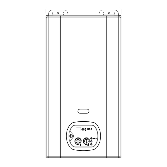
TECHNICAL CHARACTERISTICS 2.7 Control panel LEGEND ON/OFF SWITCH HEATING TEMPERATURE CONTROL KNOB D.H.W TEMPERATURE CONTROL KNOB (only for model RKR 25). OUTSIDE TEMPERATURE DISPLAY BUTTON (ONLY WITH OPTIONAL OUTDOOR SENSOR FITTED) SERVICE BUTTON. SUMMER, WINTER OR SUMMER/WINTER SELECTION BUTTON. TERMINAL BOARD FOR EXTERNAL WIRING. D.H.W FUNCTION INDICATOR (THE BOILER IS IN SUMMER OR SUMMER/WINTER MODE ) (only for model RKR 25) Hot water mode is selected FIXED LIGHT –... -
Page 17: Installation (Authorised Personnel)
INSTALLATION INSTRUCTIONS 3. INSTALLATION 3.1 Reference standard The following list is the full lists of codes of practice and British Standards That engineers should work to in the UK. It is law in the UK that a competent person installs all gas-burning appliances. Please ensure that the installer is a class of person approved for the time being by the Heath and Safety Executive for the purpose of carrying out this work. -
Page 18: Unpacking
INSTALLATION INSTRUCTIONS 3.2 Unpacking ■ The materials (cardboard) used for packing the appliance are fully recyclable. ■ It is recommended that the packing material is only removed prior to installing the boiler. The manufacturer will not be held responsible for damage caused by incorrect storage of the product. ■... -
Page 19: Installation
In order to allow access to the interior of M INIM UM DISTANCES IN mm the boiler for maintenance purposes, it is M odel important that the minimum distances RK 25 1000 indicated in figure 1 are respected. To RKR 25 1000 200 make the installation easier, the boiler is Fig. -
Page 20: Water Connections
■ The increase in temperature of the hot water storage units causes a consequent increase mod. RK 25 in volume of the water contained in them. In order to compensate for this increase in volume, the appliance is fitted with an... -
Page 21: Central Heating Circuit
INSTALLATION INSTRUCTIONS 3.5 Central heating circuit The boiler is designed for use in a sealed central heating system in accordance with the requirements of BS 5449 and BS 6798. The system should be designed to operate with flow temperatures of up to 82°C. When designing the system, the pump head, expansion vessel size, mean radiator temperature, etc. -
Page 22: Condensate Drain
INSTALLATION INSTRUCTIONS 3.6 Condensate drain Termination to an internal soil and vent pipe Boiler FAILURE INSTALL CONDENSATE DISCHARGE PIPEWORK CORRECTLY WILL AFFECT THE RELIABLE OPERATION OF THE BOILER The condensate discharge pipe MUST NOT RISE at any point along its length. There MUST be a fall of AT LEAST 2.5°... -
Page 23: Gas Connection
INSTALLATION INSTRUCTIONS 3.7 Gas connection The connection to the gas supply must be carried out by professionally qualified personnel, registered in accordance with current legislation and CORGI. When connecting the boiler to the gas supply pipe, only use appropriate gas fittings in accordance with the Gas Safety and Use Regulations.. -
Page 24: Electrical Connections
INSTALLATION INSTRUCTIONS 3.8 Electrical connections General warnings The connection to the mains power supply must be carried out by professionally qualified personnel, registered in accordance with current legislation and authorised by Radiant Bruciatori. Always check to make sure that the appliance has an efficient earth system. This requirement is only satisfied if it has been properly connected to an efficient earth system installed in accordance with the requirements of current safety standards (Standard CEI 64-8 Electrical Installations). -
Page 25: Room Thermostat - Outdoor Sensor Connections
INSTALLATION INSTRUCTIONS Electric power supply Connect the power supply to the terminal board inside the control panel as follows: a. Switch off the power supply at the main switch. b. Remove the front panel of the boiler. c. Slacken the screws and remove plate A (see fig. -
Page 26: Remote Control Connection
INSTALLATION INSTRUCTIONS 3.10 Connecting the “Remoto” thermostat/timer If the optional remote thermostat/timer has been purchased, this must be connected to the modulation board installed in the boiler control panel. To access the modulation board, proceed as follows: 1. Switch off the power supply at the main switch. - Page 27 INSTALLATION INSTRUCTIONS 6. Connect plug M1 to the interface board and plug M11 to the modulation board (fig. 7 Connect the grey and orange wires to plug M2 of the interface board and to the terminal board. 8. Connect the wires of plug M3 on the interface board to the terminal board.
- Page 28 INSTALLATION INSTRUCTIONS Regulating the Flow temperature in accordance with the outdoor temperature The outdoor sensor can be connected either to the remote control or directly to circuit board SM 20015. The sensor can thus be managed in one of two ways: •...
-
Page 29: Flue Connections
INSTALLATION INSTRUCTIONS 3.11 Flue connections In order to ensure that the appliance functions correctly and efficiently, the flue connection between the boiler and the flue terminal must be made using original components specifically designed for condensing boilers. Traditional flue components cannot be used for conveying exhaust fumes from condensing boilers, nor vice versa. - Page 30 INSTALLATION INSTRUCTIONS Flue position IMPORTANT: THE FLUE SYSTEM SHALL BE INSTALLED IN ACCORDANCE WITH THE RECOMMENDATIONS CONTAINED IN BS 5440:1. The boiler MUST be installed so that the terminal is exposed to the external air. It is important that the position of the terminal allows free passage of air across it at all times. If the terminal discharges into a pathway or passageway check that combustion products will not cause nuisance and that the terminal will not obstruct the passageway.
- Page 31 INSTALLATION INSTRUCTIONS Chimneys – UNI 7129/01 ■ distance ≤ distance > 5 m The chimney constitutes the outlet point of exhaust fumes from a single flue or from a series of branched flues. Although the chimneys may have various sizes Volume and shapes, they must nevertheless comply tecnico...
- Page 32 INSTALLATION INSTRUCTIONS kit K Flue type - Horizontal coaxial flue system Ø 100/60 in PPS polypropylene adjustable through 360 °. Discharges exhaust fumes and draws air from atmosphere. Suitable for condensing boilers only. Discharges exhaust gases and draws combustion air by means of two coaxial ducts.
- Page 33 INSTALLATION INSTRUCTIONS kit H ■ Flue type - Separate air intake/exhaust fumes discharge system in PPS polypropylene adjustable through 360°. The dual pipe system discharges exhaust fumes into a chimney and draws air from atmosphere. Suitable for condensing boilers only. Discharges exhaust gases and draws combustion air through two separate Ø...
- Page 34 INSTALLATION INSTRUCTIONS ■ kit V Flue type - Vertical coaxial flue system in PPS polypropylene. Discharges exhaust fumes and draws air directly from high Level. Suitable for condensing boilers only. Suitable for condensing boilers only. Discharges exhaust gases and draws Discharges exhaust gases and draws comburent air at roof level by means of combustion air at roof level by means...
-
Page 35: General Warnings (Flushing The System)
INSTALLATION INSTRUCTIONS 4. STARTING UP THE BOILER FOR THE FIRST TIME 4.1 General warnings The following operations must be carried out by professionally qualified personnel, registered in accordance with current legislation and authorised by Radiant Bruciatori s.p.a. The boiler leaves the factory pre-set and tested for burning either natural Gas or LPG. Nevertheless, when starting the boiler for the first time, make sure that the information on the rating plate corresponds to the type of gas being supplied to the boiler. -
Page 36: Filling The Condensate Trap
INSTALLATION INSTRUCTIONS 4.2 Filling the system JOLLY VALVE PLUG JOLLY VALVE In order to prevent scaling and eventual damage to the D.H.W heat exchanger, the CIRCULATION PUMP mains water supply must not have a hardness rating of more than 25°fr. It is nevertheless CIRCULATION advisable to check the properties of the water PUMP PLUG... -
Page 37: Starting Up The Boiler
INSTALLATION INSTRUCTIONS 4.4 Starting up the boiler Table n°1 Once the system has been filled, proceed as Gas type follows: • Check that the exhaust flue is free of G 30 10.9 obstructions and correctly connected to G 31 10.96 the boiler. -
Page 38: Parameter Table
REGULATION INSTRUCTIONS 5. COMMISSIONING THE BOILER 5.1 Parameter table PARAMETER PARAMETER OPTIONS FUNCTION N° VALUE INSTANTANEOUS BOILER SELECTS TYPE OF BOILER BOILER WITH STORAGE TANK BOILER TANK WITH +7°(stored water temp. increased by 7°) NATURAL GAS SELECTS TYPE OF GAS SETS THE CENTRAL HEATING 30-80°C FOR STANDARD SYSTEMS TEMPERATURE... -
Page 39: Parameter Programming
REGULATION INSTRUCTIONS 5.2.1 Entering Parameters Menu Each time you wish to change or check any parameter value, you should access the parameter menu, following this procedure: Place the ON/OFF switch in OFF position; Keep pressed the (▲) and (▼) buttons, switch on the boiler and wait for the display to show ‘PL’... - Page 40 REGULATION INSTRUCTIONS 5.2.2 Parameters settings To enter the parameters menu, follow the procedure shown at page n° 35 (steps 1-6). ◄ PARAMETER N° 1 – TYPE OF BOILER Use (▲) and (▼) buttons to modify the value of the parameter: 00 = Instantaneous boiler;...
- Page 41 REGULATION INSTRUCTIONS ◄ PARAMETER N° 4 – PUMP MODE ON CENTRAL HEATING PHASE Use (▲) and (▼) buttons to modify the value of the parameter: 00 = STANDARD (3 ‘ OVERRUN) 01 = ALWAYS RUNNING (to be activated ONLY FOR SYSTEM BOILERS ); Press and release the service ( S ) button to confirm your choice.
- Page 42 REGULATION INSTRUCTIONS ◄ PARAMETER N° 7 – CENTRAL HEATING PUMP OVERRUN Use (▲) and (▼) buttons to modify the value of the parameter: 00 = 0 99 = 99 x 5’’ = 450 ‘’ = 7.5’ Default value is set to 36 = 180’’ = 3’ Press and release the service ( S ) button to confirm your choice.
-
Page 43: Regulating The Gas Pressure
REGULATION INSTRUCTIONS ◄ PARAMETER N° 10 – MINIMUM HEATING POWER The value of the parameter must be equal to the one shown into page 35 table. Use (▲) and (▼) buttons to modify the value of the parameter: 24 for Natural Gas 21 for L.P.G. - Page 44 REGULATION INSTRUCTIONS 5.3 Gas data - Diagram Table n°1 – CO values Gas type G20 Natural Gas G 30 Butane 10.9 G 31 Propane 10.96 NATURAL GAS LIQUID BUTANE GAS LIQUID PROPANE GAS Table n°2 - Gas data table Lower Wobbe index (15°C; 1013 mbar) MJ/Nm 45.67 80.58...
-
Page 45: Regulating The Stepped Ignition Sequence
REGULATION INSTRUCTIONS 5.4 Regulating the stepped ignition sequence Each time the appliance is started up, in order to provide optimum ignition and an even flame distribution over the entire surface of the burner, a stepped ignition sequence is used. This consists of an instantaneous and brief increase in the gas pressure during the ignition phase only. -
Page 46: Converting The Boiler To A Different Gas Type
REGULATION INSTRUCTIONS 5.5 Converting the boiler for different gas type The conversion of a boiler from burning natural gas to LPG, or vice versa, must be carried out exclusively by professionally qualified personnel, registered accordance with current legislation. Check that the gas supply pipe is suitable for the new fuel type. -
Page 47: General Warnings
USER INSTRUCTIONS 6. MAINTENANCE 6.1 General warnings All maintenance operations must be carried out according to UNI-CIG 7129/01, and subsequent updates, by professionally qualified personnel, registered in accordance with current legislation. All warranty work is to be carried out and authorised by Radiant Bruciatori s.p.a Service centre. The RADIANT HELPLINE UK 0870 770 0414 The frequency of the boiler maintenance must comply with current law and, nevertheless, should be carried out once a year. -
Page 48: Accessing The Boiler
USER INSTRUCTIONS 6.3 Accessing the boiler All maintenance operations require one or more of the boiler casing panels to be removed. The side panels can only be removed after the front panel has been removed. Front panel: Remove the fixing screws at the lower edge of the front panel. -
Page 49: Draining The Central Heating System
USER INSTRUCTIONS 6.5 Draining the central heating system • If the need arises to drain the system, this can be done as follows: • Switch the system to “WINTER” mode and ignite the boiler. • Switch off the power supply to the boiler. •... -
Page 50: Maintenance Operations
USER INSTRUCTIONS 6.6 Maintenance operations Before carrying out any cleaning or part replacement operations, ALWAYS turn off the ELECTRICITY, WATER and GAS supplies to the boiler. Radiant Bruciatori s.p.a. will not be held responsible for damage to any of the boiler’s components caused by non-compliance with this instruction. - Page 51 USER INSTRUCTIONS Cleaning main exchanger ■ module and combustion unit (fig. 1) • Disconnect the electrical connections of the electric fan. • Disconnect the joint and remove the pipe primary heat exchanger linking the gas valve to the injector unit (venturi).
- Page 52 USER INSTRUCTIONS • Cleaning the D.H.W heat exchanger (fig. 1) d.h.w heat exchanger • Close the shut-off valve and drain the domestic hot water circuit and central heating circuit of the boiler. • Use a 4 mm Allen key to unscrew the four screws securing the heat exchanger to the multiplex unit.
- Page 53 USER INSTRUCTIONS Safety thermostat (fig. 1) • Disconnect the connecting wire. • Unscrew the fixing screws and remove the thermostat. • Replace the thermostat and re-assemble the components following the above procedure in reverse order. • Switch on the electricity, water and gas supplies central heating and restart the appliance.
- Page 54 USER INSTRUCTIONS Electric fan (fig. 1) • Remove and dismantle the entire burner unit (see venturi “cleaning the burner unit”). • Use an 8 mm spanner to unscrew the four nuts securing the electric fan to the gas manifold and then remove the electric fan, noting the positions of the gaskets and diaphragm.
- Page 55 USER INSTRUCTIONS Circulation pump (motor body) (fig. 1) • Close the shut-off valves and drain the central heating circuit of the boiler. • Use a 5 mm Allen key to unscrew the four screws circulation pump securing the motor body to the impeller body. •...
- Page 56 USER INSTRUCTIONS Modulation circuit board (fig. 1-2) circuit board scheda • Open the control panel (see “6.3 Accessing the boiler”) modulation circuit board • Disconnect all the connectors, remove the Regulating knob, unscrew the four fixing screws and remove the modulation circuit board. •...
- Page 57 USER INSTRUCTIONS Primary heat exchanger (fig. 1) camera di collegamento flue connection chamber • Close the shut-off valves and drain the central scarico fumi heating circuit of the boiler. • Switch off the power and gas supply to the boiler. •...
-
Page 58: Wiring Diagrams
USER INSTRUCTIONS 6.7 Wiring diagrams mod. RK 25 R156A TG05A056.B0306... - Page 59 USER INSTRUCTIONS mod. RKR 25 R156A TG05A056.B0306...
-
Page 60: Troubleshooting
USER INSTRUCTIONS 6.8 Troubleshooting PROBLEM POSSIBLE CAUSE REMEDY ERROR CODE NO FLAME WITH NO IGNITION NO GAS. CHECK MAINS SUPPLY. IGNITION ELECTRODE BROKEN OR EARTHED. REPLACE PART. IGNITION CIRCUIT BOARD S4565QM REPLACE PART. MALFUNCTION. REPLACE PART. GAS VALVE MALFUNCTION. REGULATE MINIMUM MECHANICAL MINIMUM ADJUSTMENT (ON GAS SLOW IGNITION. -
Page 61: Diagnostics
USER INSTRUCTIONS 6.9 Diagnostics ■ Error codes: IONISATION BLOCK SAFETY THERMOSTAT TRIPPED WATER PRESSURE ALARM HEATING SENSOR MALFUNCTION D.H.W. SENSOR MALFUNCTION 14 14 GENERAL ALARM (AIR PRESSURE SWITCH OR WATER PRESSURE SWITCH) 22 22 PARAMETER PROGRAMMING REQUEST ■ Signal codes SIGNAL CODE DESCRIPTION SIGNAL TYPE... -
Page 62: Parts List
USER INSTRUCTIONS 6.10 Parts list ■ main components PART DESCRIPTION RK 25 RKR 25 NUMBER 20042LA PRIMARY HEAT EXCHANGER GM30-80-027 20040LA 16-PLATE D.H.W HEAT EXCHANGER PAR. 561222 24029LA CIRCULATION PUMP MOTOR SCHUL 15/6-3-KU-CLF6 24046LA CIRCULATION PUMP RSL 15/6-3-KU-CLF6 WITH C1 OPEN... - Page 63 USER INSTRUCTIONS MULTIPLEX unit – mod. RKR 25 ■ 43150LA 64066LA 43139LA 54022LA 89116NA 64093LA 89116NA 64065LA 20047LA 43135LA 64068LA 89122NA 89122NA 43150LA 43145LA 43150LA 43151LA 64063LA 61004LP 64075LA 54023LA 64060LA 43139LA 43139LA 43150LA 54022LA 43150LA 43150LA 43159LA 54022LA 43139LA 96034LA 54024LA 54022LA...
- Page 64 RADIANT BRUCIATORI s.p.a. Via Pantanelli, 164/166 - 61025 Loc. Montelabbate (PU) Tel. +39 0721 9079.1 • fax. +39 0721 9079279 e-mail: tecnico@radiant • Internet: http://www.radiant.it RADIANT HELPLINE UK Technical Helpline - 0870 770 0414 Spares - 0870 770 0425 Email - info@portsdean.co.uk THE TECHNICAL DATA AND MEASUREMENTS ARE PROVIDED FOR INFORMATION PURPOSES ONLY AND ARE NOT BINDING.
Need help?
Do you have a question about the RK 25 and is the answer not in the manual?
Questions and answers