Advertisement
Table of Contents
- 1 Operating Manual
- 2 Table of Contents
- 3 Mounting the HDC Controller
- 4 Connecting Valve
- 5 Wires to Controller
- 6 Connecting Power Source
- 7 Programming the Controller
- 8 Dial Positions and Functions
- 9 Manual Station/Program
- 10 Erasing Controller Memory
- 11 Trouble Shooting Guide
- 12 Display Icons
- Download this manual
Advertisement
Table of Contents

Summary of Contents for Hit Productsc Rain Pro
-
Page 1: Operating Manual
Rain Pro Intelligent Irrigation Solutions Controller Operating Manual 4 or 6 Station Hit Products Corporation P. O. Box 929 • Lindsay, CA 93247 Phone: (559) 562-5975 Read Entire Instruction Booklet Before Installation English December 2012... -
Page 2: Table Of Contents
TABLE OF CONTENTS Mounting the HDC Controller ........ 4 Connecting Valve ............ 4 Wires to Controller ..........4 Connecting Power Source ........5 Master Valve/Pump Start/Sensor ....... 6-7 Programming the Controller ........8 Schedule/Calendar Options ......13-14 Dial Positions and Functions ....... 15 Manual Station/Program ......... -
Page 3: Mounting The Hdc Controller
MOUNTING THE HDC CONTROLLER Locate controller within 5 ft. of a standard electrical outlet that provides continuous, uninterrupted power. Do not install controller within 15 ft. of a pump, pump start relay or any high voltage junction boxes or elec- tric motors. -
Page 4: Connecting Power Source
Wire sizing should be of significant size to allow a maximum of 5 volts drop between controller and valves. Use Ohms’ Law to calculate wire voltage drop. Replace cover. Note: All in-field wire splices should be made using a dry type waterproof, gel-filled Hit Products DBC-Y type connector or equivalent. - Page 5 MASTER VALVE/PUMP START WIRING If a master valve or pump start relay is being used in conjunction with this controller, wire as follows. Connect one wire to the “MV” terminal and one to the “Com” terminal. If using a pump start relay, it must be; a) Located at least 15 feet from controller.
- Page 6 SENSOR WIRING A rain sensor or any other type of normally closed micro-switch sensor may be used in conjunction with this controller. Sensor activation will interrupt controller output. Remove lower cover. Route the 2 wires from the sensor to the bottom of the controller and connect one each wire to the two “RS”...
- Page 7 DEFAULT PROGRAM, POWER FAILURE, LOW BATTERY OR NO BATTERY INSTALLED The controller does not require a default program after a power outage. The controller has non-volatile memory to retain your custom program. Four AAA Alkaline bat- teries maintain the real time clock and calendar. (Batteries should be changed annually.) Should there not be sufficient battery power to maintain the real time clock and calendar and there is a power...
- Page 8 Note: The controller will Run scheduled programs according to the displayed Day and Time. You will need to reset the controller to current time and calendar. DISPLAY CURRENT CONDITION NOPO No AC power to controller LOBA Low battery or no battery NOPO will blink on-off it no AC power is available and battery is installed and charged.
-
Page 9: Programming The Controller
PROGRAMMING THE CONTROLLER To successfully program controller, all three programming elements must be completed. They are: Program Start Times (Time of day a complete programmed irrigation cycle will start). Station Run Times (The length of time each station/valve will irrigate). Calendar/Schedule (The days of week/calendar that you desire to irrigate). - Page 10 To program the controller, you are provided + or – buttons that will change the value of the “Flashing display”. The ← or → change the subject of information that is flashing. The subject or “Flashing display” is in sequence and can be scrolled forward →...
- Page 11 INPUT THE CURRENT DATE AND TIME Turn the dial to the CURRENT DATE/TIME. Use the + and – buttons to select the current year. Push the → button to activate the month. The month will be flashing. Use the + and – buttons to select the current month.
-
Page 12: Setting Program Start Times
SETTING PROGRAM START TIMES Rotate the dial to program “START TIMES”. Choose program A, B or C. To change program from existing program, push the PRG button. Use the + and – buttons to adjust to desired start time. Start times are available every 15 minute increment of the hour. - Page 13 If two or more programs are to start at the same time, only the first program will start and run. At the completion of that program running, the next program will run, and so on until all multiple start times are run. This is called “stacking”. ESTABLISHING INDIVIDUAL STATION RUN TIMES This is the setting for establishing how long each...
-
Page 14: Setting The Calendar
Press the → button to go to the next station. Repeat steps 3 and 4 for each station that is to be active on each specific program. For stations/valves that are to be inactive on each specific program, put “Station Run Time”... -
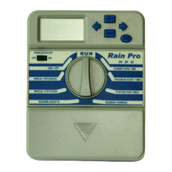
Page 15: Dial Positions And Functions
Repeat step 3 for each day of the week. The → button may be used to advance to a particular day of the week. To operate “odd” or “even” days of the month, continue advancing the → button and then activate “odd”... -
Page 16: Manual Station/Program
MANUAL STATION To manually activate a single station for one watering cycle for a programmed length of time. Rotate dial to “Manual Station”. Push → to desired station number. Push + or – buttons to input length of time, this station will now operate this programmed time. - Page 17 Push the → button to choose the first station in the sequence of the manual program to start. The “run time” for each station will be displayed as currently programmed. For this cycle only, you can customize each station run time without effecting the individually programmed station run times within a program.
- Page 18 SEASONAL ADJUST The seasonal adjust feature provides a one step universal run time adjustment in 10% increments up or down for all programs. It effects all station run times in all programs. In hotter, drier weather, you can increase the water budget in 10% increments up to 200% of originally programmed station run times.
-
Page 19: Erasing Controller Memory
RE-SETTING OR ERASING CONTROLLER MEMORY If you want to eliminate all past programming input to controller, as if to start over as new, with no data in controller, proceed as follows: Press the →, the – button and the PRG buttons simultaneously. -
Page 20: Trouble Shooting Guide
TROUBLE SHOOTING GUIDE No Display Check AC Power Supply, power at the controller information. should be 24-26 VAC. Check AC wiring. Check power at wall plug. Display reads Slide Rain Sensor switch to “off ” or install a sensor “Sensor Off ”. jumper wire on terminal strip connecting “RS”... -
Page 21: Display Icons
ICONS ON THE THC DISPLAY Icon Description 1) % Indicates Seasonal Adjust. 2) AM Indicates time of day AM or PM. 3) PM Indicates time of day AM or PM. 4) TIME Displayed to set current time. - Page 22 5) MONTH Displayed to set current month. 6) YEAR Displayed to set current year. 7) RUN Displayed to indicate program is running. 8) DAY Displayed to set current day. 9) SENSOR Automatic operation is suspended by rain sensor. PROGRAM is displayed to change program.
- Page 23 STATION Displayed when programming the station. START TIME Displayed when programming the start time. Displayed for programming watering day or non-watering day in the “calendar” Indicates active day Indicates non-active day. 18-24) Displayed for programming watering day. Displayed for programming ODD day watering schedule.
- Page 24 RAIN ® Intelligent Irrigation Solutions...
Need help?
Do you have a question about the Rain Pro and is the answer not in the manual?
Questions and answers