Table of Contents
Advertisement
Advertisement
Table of Contents

Related Manuals for MOOSE Z1250


Summary of Contents for MOOSE Z1250
- Page 1 MOOSE Z1250 Security System Control User Guide Table of Contents...
- Page 2 Guidelines 1. Read this entire manual and keep it in a secure place. 2. The system must be tested at least once per week to ensure proper operation. Contact your security representative for testing procedures and scheduling of a regular maintenance program.
-
Page 3: Table Of Contents
Contents 1.0 Introduction........................2 2.0 LCD Overview......................3 3.0 Normal Arming & Disarming...................4 3.1 To Arm.........................4 3.2 To Disarm......................5 4.0 System Not Ready To Arm..................6 4.1 Option 1: Force Arming..................6 4.2 Option 2: Bypassing....................8 5.0 Quick Commands....................10 5.1 Quick Arming....................10 5.2 Quick Disarming....................11 5.3 Quick Arming Level Change................12 5.4 Quick Force Arming..................13 6.0 What To Do If The Alarm Is Sounding..............14... -
Page 4: Introduction
Introduction By purchasing this security system, you have taken a major step toward protecting your home or business. Read these instructions carefully to familiarize yourself with the system. Your system has been custom designed to meet your specific requirements and may include features not discussed in this manual. -
Page 5: Lcd Overview
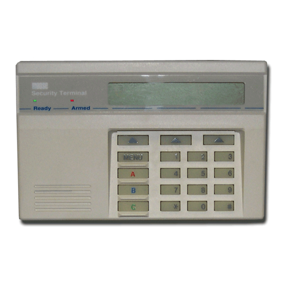
LCD Overview Figure 1 – LCD Control Station 1. Status Indicator Ready: On-System is ready to arm. Off-System is not ready to arm. Armed: On-Intrusion detection system is armed. Off-Intrusion detection system is disarmed. Blinking-A burglar alarm has occurred 2. Menu Key Allows the user to scroll through available menu options. 3. -
Page 6: Normal Arming & Disarming
Normal Arming & Disarming When the system is disarmed and all zones are secure (all contacted doors, widows, etc. closed), the LCD displays AREA 1 READY TO ARM. Since the area name “AREA 1” is often customized at the time of installation, your display may be slightly different. -
Page 7: To Disarm
• ARMED NITE Perimeter and selected interior zones armed with entry time. • ARMED NITE INST Perimeter and selected interior zones armed with no entry time. Figure 2 – Normal System Arming 3.2 To Disarm Select the DISARM soft key. At the ENTER PASSCODE prompt, enter your user code and press the ENTER soft key. -
Page 8: System Not Ready To Arm
System Not Ready To Arm When one or more intrusion zones are faulted (a contacted door or window is not properly closed, for example), the LCD indicates AREA 1 NOT READY and gives you the option to DISPLAY the name of each faulted zone. - Page 9 Figure 4 – Force Arming Glossary Table of Contents...
-
Page 10: Option 2: Bypassing
4.2 Option 2: Bypassing If this programming option is enabled, after you select ARM, enter your passcode and select the arming level, the display indicates that the system is not ready and gives you the option to DISPLAY the violated zones. This display screen is where you get the option to BYPASS faulted zones. - Page 11 Figure 5 – Bypassing Glossary Table of Contents...
-
Page 12: Quick Commands
Quick Commands Quick commands are included in this system as a convenience feature. They enable the engaging of certain functions with fewer keystrokes than the conventional procedure. The following paragraphs outline the procedures for Quick Arming, Quick Disarming, Quick Arming Level Change and Quick Force Arming. -
Page 13: Quick Disarming
5.2 Quick Disarming From the armed LCD menu screen, enter your user passcode without pressing the DISARM soft key. Then press the DISARM soft key. Figure 7 – Quick Disarming Glossary Table of Contents... -
Page 14: Quick Arming Level Change
5.3 Quick Arming Level Change You may occasionally wish to change the system’s arming level (AWAY, STAY, NIGHT) while the system is armed. Unlike many security systems, this system has a feature that allows you to change the arming level without completely disarming and then rearming the system. -
Page 15: Quick Force Arming
5.4 Quick Force Arming To Quick Force Arm the system, enter you user code without pressing ARM. Choose the arming level as you would in a regular arming procedure. When the system displays NOT REAY TO ARM, press the “#” key to force arm the system, i.e., to arm the system “around”... -
Page 16: What To Do If The Alarm Is Sounding
What To Do If The Alarm Is Sounding The display indicates that an intrusion has occurred. 1. Press SILENCE. 2. Enter your user code. If you make an error entering your code, press CLEAR and reenter the code. 3. Press the soft key corresponding to ENTER. The LCD then displays the first zone that went into alarm. -
Page 17: Trouble Conditions
Trouble Conditions If a trouble condition exists, the LCD blinks back and forth between a system trouble message and the area’s status. Some trouble conditions also produce an audible alarm. When more than one trouble condition is present, the display scrolls through the trouble conditions and the area’s status, pausing two seconds for each item displayed. -
Page 18: Trouble Conditions When The System Is Armed
7.2 Trouble Conditions When the System Is Armed Defining trouble conditions when the system is armed requires a slightly different procedure. It is necessary to enter a user code before the system displays the detailed trouble condition(s). However, in this procedure, entering the user code automatically silences all audible alert tones. -
Page 19: Auxiliary Panic Keys
Auxiliary Panic Keys The three keys on the left side of the keypad face are Auxiliary Panic Keys. The functions activated by these keys have various uses. Most are used as distress signals and always work regardless of whether or not the system is armed. -
Page 20: Menu Features And Definitions
Menu Features and Definitions The system has menu selections that enable you to perform a variety of functions, including user level programming. The menu key allows you to scroll through the available options. Note: Flowcharts detail the procedures for accessing the menu features described in this chapter. -
Page 21: Functions Accessed By The First Menu Press
9.1 Functions Accessed by the First Menu Press RESET ALARM: Reset silent Holdup Alarms only. You must perform this function or a disarm of the entire area to get a new Holdup Alarm. See Chapter 8.0 for a review of Holdup Alarms. Figure 16 –... -
Page 22: Functions Accessed By The Second Menu Press
ENABLE CHIME: Provides an audible annunciation from the control stations(s) when certain doors and/or windows in the protected area are opened while the system is disarmed. The feature is commonly used for residential door annunciation or as customer entry notification in retail establishments. - Page 23 Note: The Event History displays only the events occurring in the area(s) accessible to the user code entered. Figure 19 – Event History Procedure Glossary Table of Contents...
- Page 24 EXTENDED CLOSING: Permits you to delay the Auto Arm time only by one hour or extend the Late to Arm window by one hour. Extended Closing can only be activated once per day and can never extend past midnight. Activation of this function is reported to the central station and is posted in the event log.
-
Page 25: Functions Accessed By The Third Menu Press
9.3 Functions Accessed by the Third Menu Press KEYPAD OPTIONS: Allows you to adjust beeps, adjust lamp, and change the viewing angle of the screen for the keypad in use. Lamp adjustments may not be operational on some keypads. The AC Fail Light lamp adjustment allows you to set a keypad to provide light during a power failure or to be dim to conserve the system’s battery. - Page 26 PROG OPTIONS: The master code is required to access this option. Allows access to the following fields: USER CODES: Allows you to set and change user codes. (See Chapter 10.0 User Codes) SCHEDULE EVENTS: Allows the master user to set up or alter the schedule for the area’s opening and closing times.
- Page 27 SYSTEM TEST: Allows the testing of various aspects of the system. When you press this all audible and visual indicating devices (alarms, etc.) assigned to the area being tested activate for two seconds. The LCD displays the number of zones in the area that have been tested and the number of zones yet to be tested.
-
Page 28: Functions Accessed By The Fourth Menu Press
9.4 Functions Accessed by the Fourth Menu Press SET CLOCK: Allows you to adjust the system’s clock. Use the left and right arrow keys to move the cursor through the field. Use the numeric keypad to enter the digits for month, day, year, hour, minute, and second. Press the QUIT to return the display to the status screen. -
Page 29: User Codes
10.0 User Codes 10.1 Programming User Codes Passcodes may be programmed at the user level. However, only a master user code (highest authority level) is allowed access to user programming mode. 1. Press the menu key three times to display Menu 3. 2. - Page 30 4. Press the USER CODES soft key. The screen displays the programmed information of the first user code. Only the user codes that share the same area assignment as the master code are displayed. 5. To change a displayed code, simply enter the new digits. As you enter digits, the new code appears in the lower tight corner of the display.
- Page 31 Figure 26 – Numeric Keypad Key Characters: 1= 0 1 2 3 4 5 6 7 8 9 : ; ? < = > ? @ 6= M N O 2= A B C 7= P Q R S 3= D E F 8= T U V 4= G H I 9= W X Y Z...
-
Page 32: Deleting A User Code
Note: Pressing the number “#” key when the cursor is positioned in the User Name field changes the prompts at the bottom of the screen. The possible combinations are: Figure 27 – User Name Field Promp 8. To advance to another code, press NEXT. 9. -
Page 33: Temporary Codes
10.3 Temporary Codes The installer may designate an optional temporary code (Authority Level 4) in your system. This code, designed as a convenience feature, allows restricted access to the system. It is for use by people (baby-sitters, maintenance personnel, etc.) to whom you may wish to give limited, temporary access to the area protected by your security system. -
Page 34: Led Keypad Operation
11.0 LED Keypad Operation Your system may be equipped with an LED keypad. This type keypad allows you to operate the control in a very simple manner and is limited to AWAY level arming. The keypad can arm, disarm, view system status and perform access. -
Page 35: Fire Detection
12.0 Fire Detection Your system may include fire detection, depending upon purchased options and the local regulations for your area. If so, please notify your local fire department that a fire alarm system has been installed. Fire systems require regular testing and maintenance. Common household dust buildup in smoke detectors can cause them to false alarm or fail in a time of need. -
Page 36: Appendix I Schedule Events Definitions
Appendix I SCHEDULE EVENTS Definitions Many options are accessible under the Schedule Events menu. From the third menu key press screen, select PROG OPTIONS. Enter your passcode as prompted. Select the SCHEDULE EVENTS option. From the AREA SCHEDULE screen, press SELECT to program this menu. IMPORTANT: Automatic Arming and Disarming must not be programmed for the same days as Scheduled Maintenance Arming and Disarming. - Page 37 A1 AUT ARM DAYS..{SMTWTFS} Automatic Arming: Select the day(s) of the week that the system automatically arms. A2 AUT DIS DAYS..{SMTWTFS} Automatic Disarming: Select the day(s) of the week that the system automatically disarms. SCHEDULED MANUAL ARMING AND DISARMING These items are used to set up daily schedules for authorized opening and closings.
- Page 38 A1 CLOSE TIME TUE: 00:00/___ Programmed time for automatic arming or scheduled closing on Tuesday. A1 CLOSE TIME WED: 00:00/___ Programmed time for automatic arming or scheduled closing on Wednesday. A1 CLOSE TIME THU: 00:00/___ Programmed time for automatic arming or scheduled closing on Thursday. A1 CLOSE TIME FRI: 00:00/___ Programmed time for automatic arming or scheduled closing on Friday.
-
Page 39: Appendix Ii Fire Protection Information
Appendix II Fire Protection Information The following information is from the National Fire Protection Association (NFPA) Standard 72. • In Case of Fire Leave immediately! Don’t stop to pack or search for valuables. In heavy smoke, hold your breath and stay low. Crawl if necessary. The clearest air is usually at the floor. - Page 40 It is important that children be instructed carefully. They tend to hide in crisis situations. Train children in proper fire evacuation procedures. Become familiar with the distinctive sounds of your fire and burglar alarm signals. Your installer can demonstrate the different audible signals emitted by your particular system.
- Page 41 Smoke Detector Locations Glossary Table of Contents...
-
Page 42: Glossary
Glossary ACCESS: A system feature that allows one or more keypads to be used as access control devices. AC POWER: Alternating current supplied from the plugged-in transformer. AREA: The region of the premises protected by the security system. ARM: To turn the intrusion detection system on. AUTHORITY LEVEL: A designation assigned to each user code that determines which specific functions can be accessed by that user. - Page 43 Index AC POWER FAILURE Fire Alarm 17, 33 adjust beeps Fire CIRCUIT trouble adjust lamp 23 Fire Detection 33 Alarm Fire Hazards Alarm LED Fire Initiating Circuits Fire Panic Key ARMED Fire Prevention ARMED INST Fire Protection Armed LED fire system audibles ARMED NITE fire system test ARMED NITE INST...
- Page 44 Normal System Disarming system ready not ready System Reference Guide 17, 33 Numeric Keypad SYSTEM TEST panic. See emergency panic Third Menu Press Panic Keys time Passcodes Trouble Condition perimeter zones Trouble Conditions power light Trouble LED pre-alarm delay PRINT USER CODES PROG OPTIONS 24, 27...
- Page 45 NOTES Table of Contents...
- Page 46 NOTES Table of Contents...
-
Page 47: System Reference Guide
System Reference Guide Emergency Telephone Numbers Police Fire Neighbor Doctor Central Station Service Rep. Delay Times Seconds of exit delay time for Zone(s) Seconds of entry time (Delay 1) for Zone(s) Seconds of entry time (Delay 2) for Zone(s) Central Station Information Subscriber Number Features Enabled Intrusion...
Need help?
Do you have a question about the Z1250 and is the answer not in the manual?
Questions and answers