Table of Contents
Advertisement
Quick Links
Advertisement
Table of Contents

Related Manuals for Soundfield DSF-2


Summary of Contents for Soundfield DSF-2
-
Page 1: User Guide
SOUNDFIELD DSF-2 Broadcast Microphone System User Guide Version 1.12 System comprises: • DSF-2 1U Digital Microphone Controller • DSF-2 Microphone in Leather Case • 20m SoundField Microphone Cable • Shockmount • Mains Power Cable • Owners Manual... -
Page 2: Table Of Contents
Rycote Assembly Instructions 14-16 A Practical Guide For Use on 5.1 Outside Broadcasts 17-19 Interfacing the DSF-2 with the DSF-3 for Live Surround Broadcast Specification - Warranty Shipping and Quality Assurance 12 Pin Connector Wiring Details for SoundField Microphone Cables... -
Page 3: Safety Information
SoundField DSF-2 User Guide SAFETY INFORMATION • This equipment must be EARTHED. • Only suitably trained personnel should service this equipment. • Please read and take note of all warning and informative labels. • Before starting any servicing operation, this equipment must be isolated from the AC supply (mains) by removing the incoming IEC mains connector. -
Page 4: Introduction
When used is conjunction with the 250m SoundField mic cable, the microphone head can be situated up to 1.25 Kilometres from the DSF-2 controller. This can be a major benefit in situations where the OB vehicles have to be sited some distance away from the venue or performance. -
Page 5: How Does It Work
The four outputs from the capsules of SoundField microphones (called SoundField A-Format audio signals) are converted by the DSF-2 processor into four components known as SoundField B-Format. These convey all of the information of the entire sound field, and are the three directional vectors - Left/Right, Front/Rear and Up/Down - and absolute pressure. -
Page 6: How Does It Work
By recording the four B-Format outputs from the DSF-2 controller these components can be preserved for subsequent production and processing of current and all future surround formats. -
Page 7: Getting Started
The DSF-2 system does not require Phantom Power (48V) if it is connected to a mixing console. Please ensure that the Phantom Power on the mixer input channels is turned off. - Page 8 KEYS TO PROPER PLACEMENT OF SOUNDFIELD MICROPHONES Getting the mic in the right place is the first step in making a good recording. With SoundField microphones, it is too easy to be lulled into complacency by the excellent stereo and surround sound pick-up they provide.
-
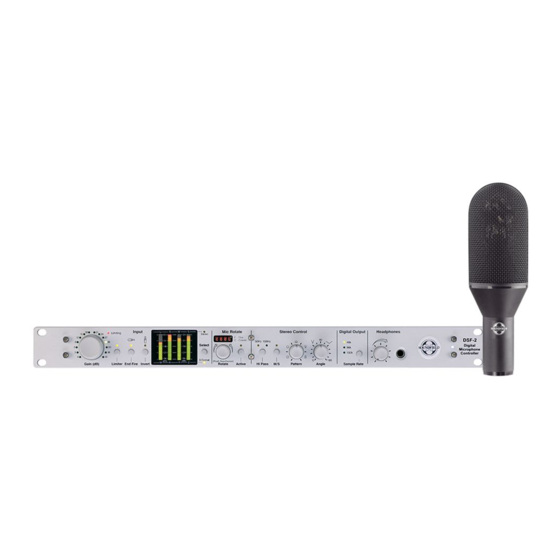
Page 9: Controls
SoundField DSF-2 User Guide CONTROLS INPUT SECTION - provides all parameters relating to gain, microphone pick-up orientation and bargraph metering. 1. Gain The Relay Switched Gain control adds up to a further 40dB of microphone gain in 3dB steps. A circular LED display illuminates the selected gain position. - Page 10 SoundField DSF-2 User Guide Up/Down height information being reversed. It is important to document the status of the Invert switch when making B-Format recordings for later post production. 5. Bargraph Metering The four bargraph meters are switchable to monitor either the four B-Format signals (W, X, Y and Z) or the stereo Left/Right and Mid-Side.
- Page 11 SoundField DSF-2 User Guide STEREO CONTROL SECTION - the controls in the Stereo Section have no effect on the four B-Format output signals. 1. Hi Pass A switchable 50Hz or 100Hz high pass filter is available to attenuate unwanted low frequency rumble or wind noise.
- Page 12 DIGITAL OUTPUT Sample Rate The DSF-2 system will operate at the current broadcast sample rate standard of 48K and in addition offers 96K and 192K sample rates. A sample rate selector button enables the user to cycle through the sample rate options and a green status LED displays the selected sample rate.
-
Page 13: Controls
(Pin 1 = ground, Pin 2 = + (positive) and Pin3 = - (negative). 5. MIC INPUT - Lemo 12 pin female panel mount connector. The DSF-2 system will drive up to 250m of SoundField mic cable with no loss of quality or signal level. -
Page 14: Rycote Assembly Instructions
SoundField DSF-2 User Guide RYCOTE ASSEMBLY INSTRUCTIONS DSF-2 Microphone and Rycote kit in flightcase. Remove end of Windshield by turning in an anti-clockwise direction. Loosen the two black plastic bolts situated on the Pistol Grip under the Windshield. Remove Windshield by gently sliding away from the Pistol Grip. - Page 15 SoundField DSF-2 User Guide Insert microphone into the inner cradle. IMPORTANT: WHEN THE MIC IS RIGGED IN ITS FINAL POSITION IN THE STADIUM FOR END-FIRE USE, THE SOUNDFIELD LOGO ON THE MIC BODY MUST BE FACING DOWNWARDS. SoundField logo facing downwards When microphone is fully inserted, tighten the two Allen bolts with the Allen key provided.
- Page 16 SoundField DSF-2 User Guide Connect microphone cable ensuring that the red dot on both the microphone and cable connector are lined up. Insert the microphone cable into the groove provided on the underside of the Windshield before replacing end of Windshield. Ensure the Windshield end is securely located in its original position.
-
Page 17: A Practical Guide For Use On 5.1 Outside Broadcasts
A PRACTICAL GUIDE FOR USE ON 5.1 OUTSIDE BROADCASTS by Robert Edwards, VSS Ltd. Only now have the true benefits of SoundField microphones become apparent to the sound mixers in the live television community who are now being asked to deliver 5.1 audio and more, to accompany live High Definition Broadcasts. - Page 18 “End-fire” mode, and the “End-fire” switch on the Control Unit should be selected. If the microphone is rigged so that the SoundField badge is upward, then the “Invert” switch must be selected. The multi-pin cable is connected from the microphone to the Control Unit. This outputs four channels of SoundField “B-Format”...
-
Page 19: A Practical Guide For Use On 5.1 Outside Broadcasts
SoundField DSF-2 User Guide The SoundField has a very low noise-floor and can cope with a wide dynamic range. This is good, since the crowd reactions of sporting events also tend to have a wide dynamic range. The gain is best set while the stadium is performing tests on the PA system for safety announcements, as these are generally very loud and offer a guide to the high SPL achieved in the stadium. -
Page 20: Interfacing The Dsf-2 With The Dsf-3 For Live Surround Broadcast
If post-production capability is required at a later date for the audio material it is essential to record the four B-Format signals. A live stereo feed is provided by the DSF-2 or the DSF-3 will provide a stereo feed in post-production. -
Page 21: Specification
SoundField DSF-2 User Guide SPECIFICATION Audio Specification - Control Unit Analogue Inputs: maximum input level 26.5dBu Analogue Limiter: when enabled threshold set to 24.5dBu Analogue Bandwidth: 10Hz – 40KHz +/- 0.1dB Analogue to Digital Converter: 2 x CS5381 Supported Sample rates: 44.1K, 48K, 88.2K, 96K, 176.4K and 192K Mic Pre/Analogue to Digital Converter performance: All performance specifications are rms, un-weighted and band limited 20Hz –... -
Page 22: Warranty
What to do if a fault is found If a fault develops in the unit, notify SoundField Ltd. or their nearest service facility giving full details of the difficulty. On receipt of this information, service or shipping instructions will be forwarded to you. No equipment should be returned under the warranty without prior consent from SoundField Ltd. -
Page 23: Shipping And Quality Assurance
If the unit is returned the original container should be used. If this is not possible, a new container can be obtained from SoundField Ltd.; please specify the model number when requesting a new container. If the specially designed container is not used ensure that a suitable rigid container of adequate size is used, wrap the instrument in paper and surround it with a good thickness of shock absorbing material. -
Page 24: Pin Connector Wiring Details For Soundfield Microphone Cables
SoundField DSF-2 User Guide 12 PIN CONNECTOR WIRING DETAILS FOR MICROPHONE CABLES 12 Pin Male 12 Pin Female Pin 1 LB (+) Pin 1 Pin 2 LB (-) Pin 2 Pin 3 RB (+) Pin 3 Pin 4 RB (-)
Need help?
Do you have a question about the DSF-2 and is the answer not in the manual?
Questions and answers