Table of Contents
Advertisement
Advertisement
Table of Contents

Related Manuals for Wavelength Electronics LFI-3500 Series


Summary of Contents for Wavelength Electronics LFI-3500 Series
- Page 1 LFI-3500 Series Temperature Controllers User’s Guide...
- Page 3 LFI-3500 Series Temperature Controller User’s Guide Publication number 92-130002D © Copyright 1996, 1997, Wavelength Electronics, Inc. P O Box 865, Bozeman, MT 59771 All Rights Reserved Printed in U. S. A.
- Page 4 LFI-4500's laser diode driver output if the temperature controller output is turned off for any reason. Interlock any combination of LFI-3500 series temperature controllers or LFI-4500 series laser diode drivers without additional hardware. Two or more modules mount into a 19"...
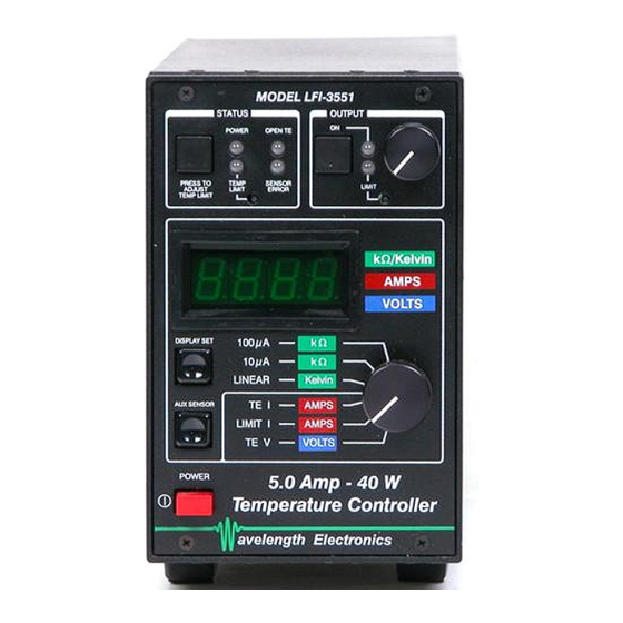
- Page 5 LFI 3500 Series Selection Guide Model Description LFI-3525 15 W, 2.5 Amp, 6 Volt, Temperature Controller LFI-3526 22 W, 2.5 Amp, 9 Volt, Temperature Controller LFI-3550 25 W, 5.0 Amp, 5 Volt, Temperature Controller LFI-3551 40 W, 5.0 Amp, 8 Volt, Temperature Controller Each model includes: 9&15 pin D-sub receptacles with shielded covers and hardware, user guide, and AC power cord.
-
Page 6: Default Configuration From The Factory
Default Configuration from the Factory The following are the factory default settings. Rear Panel: CONFIGURATION SWITCH: 2 3 4 5 6 7 CONFIGURATION Sensor setting: Thermistor, 100µA reference current Loop Direction: NTC, for thermistors PID Constants: P = 32, I = 1 second, D = OFF Temperature Limit = HIGH Front Panel: LIMITS:... -
Page 7: Table Of Contents
TABLE OF CONTENTS Default Configuration from the Factory ___________ 6 Safety Summary ______________________________ 8 Front Panel At a Glance _______________________ 10 Rear Panel At a Glance _______________________ 12 Preparing the Temperature Controller for Use_____ 15 Operating Guidelines _________________________ 16 Operation with Thermistors __________________ 16 Operation with the AD590____________________ 18 Operation with the LM335____________________ 20 Operation with RTDs________________________ 22... -
Page 8: Safety Summary
Safety Summary Do not install substitute parts or perform any unauthorized modification to the product. Return the product to Wavelength Electronics for service and repair to ensure that safety features are maintained. Do not use this product beyond its specifications. - Page 9 Complete all operational steps in the order provided. Skipping a step can result in damage to the device being controlled or NOTE! the Thermoelectric Module. Start with the section appropriate to the type of sensor you are using WARNING For continued protection against fire, replace line fuse only with fuse specified, type and rating.
- Page 11 Temp Limit LED: This LED lights red whenever the load temperature exceeds the limit temperature set by the Temp Limit Trimpot. The output current is switched off when this error occurs. Temp Limit Trimpot: This adjusts the Temp Limit Setpoint. Sensor Error LED: This LED lights red whenever the sensor voltage is either greater than 5V or less than 0.2V.
- Page 13 Configuration Switch Bank: This ten position switch bank configures the type of sensor used, the feedback P, I, and D terms, and sets the temperature limit to a HIGH or LOW limit. 2 3 4 5 6 7 CONFIGURATION Switches 1, 2, & 3: (10µA, 100µA, and 1000µA) Determines reference current through the sensor.
- Page 14 Analog Interface Connector: ANALOG 50 Ω Terminator INPUT BNC & 15 pin D-sub plug ANALOG INTERFACE Pins 1 & 2: (Mod+, Mod-) External analog input. The BNC input is in parallel, but isolated by two 1kΩ resistors. Either of the inputs can be used, but not simultaneously.
-
Page 15: Preparing The Temperature Controller For Use
Preparing the Temperature Controller for Use Check the list of supplied items: One Power cord One 9 pin D-Sub receptacle (solder cup), hood, and connecting hardware One 15 pin D-Sub receptacle (solder cup), hood, and connecting hardware One AC Fuse installed One AC Fuse is shipped separately. - Page 19 Step 4: Select the PID Constants The most common PID settings for the AD590 are: P - Gain = 64 I - Integral Time Constant = 10 seconds D - Differential Time Constant = NONE For more detailed PID setup, see page 28. Step 5: Set the HIGH or LOW Temperature Limit See page 26 for this operation detail.
- Page 21 Step 5: Set the HIGH or LOW Temperature Limit See page 26 for this operation detail. Step 6: Adjust the LIMIT Current See page 25 for this operation detail. Step 7: Adjust the Temperature Setpoint Rotate the Display Select Switch to the LINEAR. The value displayed will be the ambient temperature in Kelvin.
- Page 23 Step 5: Set the HIGH or LOW Temperature Limit See page 26 for this operation detail. Step 6: Adjust the LIMIT Current See page 25 for this operation detail. Step 7: Adjust the Temperature Setpoint Rotate the Display Select Switch to either the 10µA or 100µA position. The value displayed will be the resistance of the RTD at ambient temperature.
-
Page 28: Further Information
Configure the PID Constants Switch 8 Switch 7 Switch 6 Setpoint + Mod. Input To Output Sensor Power Feedback Amplifier Error Term Switch 9 Error Amplifier PID Processor ERROR AMPLIFIER: The error amplifier section provides the difference between the setpoint temperature and the actual temperature of the load device as sensed by the temperature sensor. -
Page 30: Practical Pid Setups
Practical PID Setups: Definitions: Small Thermal Load: Q < 5 Watts Medium Thermal Load: 5 W < Q < 20 Watts Large Thermal Load: Q > 20 Watts is the heat pumped from the TE’s cold surface. Typical Settings for Thermistors Small Thermal Load P = 16, I = 1 sec, D = none 2 3 4 5 6 7... -
Page 31: Error And Status Indicators
Error and Status Indicators Several LED indicators and a beeper are used to determine the status of the controller. Status Section Power LED: This LED lights green whenever the AC Power Switch on the front panel is depressed and AC power is supplied to the unit. Temp Limit LED: This LED lights red whenever the load temperature exceeds the Limit Temperature as set by the Temperature Limit Trimpot (see... -
Page 32: Analog Interface
Analog Interface Pins 1 & 2: (Mod+, Mod-) An external analog signal can be directly connected to these pins (or the Analog BNC Input) to remotely control temperature setpoint. This input is configured to accept ± 10 V signals while withstanding inputs as large as ±... - Page 33 Pins 8 & 9: (On/Off Detect, Common) This pin is an open drain connection that remains in a high impedance state when the output is disabled. When the output is enabled, this output is forced into a low impedance state with respect to the common connection (pin 9).
-
Page 34: General Specifications
LFI 3500 General Specifications Power Supply: 115 or 230 VAC ±15% 50 or 60 Hz (switch selectable on rear panel) Maximum AC Input: 250VAC Power Consumption: 160VA Peak Size (W x D x H) 106 mm x 300 mm x 163 mm (4.25"... -
Page 35: Electrical Specifications
LFI-3500 ELECTRICAL SPECIFICATIONS MODEL NUMBER LFI-3525 LFI-3526 LFI-3550 LFI-3551 TEC OUTPUT Output Control Loop Type Bipolar, PID Bipolar, PID Bipolar, PID Bipolar, PID ± ± 2.5 A ± ± 2.5 A ± ± 5.0 A ± ± 5.0 A Maximum Output Current ±... -
Page 36: Mechanical Specifications
MECHANICAL SPECIFICATIONS... -
Page 38: Warranty
The information contained within this document is subject to change without notice. Wavelength Electronics makes no warranty of any kind with regard to this material, including, but not limited to, the implied warranties of merchantability and fitness for a particular purpose.
Need help?
Do you have a question about the LFI-3500 Series and is the answer not in the manual?
Questions and answers