Sony CDP-C591 Service Manual
Hide thumbs
Also See for CDP-C591:
- Service manual (28 pages) ,
- Operating instructions manual (20 pages)
Table of Contents
Advertisement
CDP-C591/CE235/CE335
SERVICE MANUAL
Compact Disc Player
Laser
Semiconductor laser (λ = 780 nm)
Emission duration: continuous
Laser output
Max 44.6 µW*
* This output is the value measured at a distance of
200 mm from the objective lens surface on the
Optical Pick-up block with 7 mm aperture.
Frequency response 2 Hz to 20 kHz ± 0.5 dB
Signal-to-noise ratio More than 102 dB
Dynamic range
More than 98 dB
Harmonic distortion Less than 0.0045%
Output
Jack
type
LINE OUT
Phono
jacks
DIGITAL OUT
Optical
(OPTICAL)
output
connector
MICROFILM
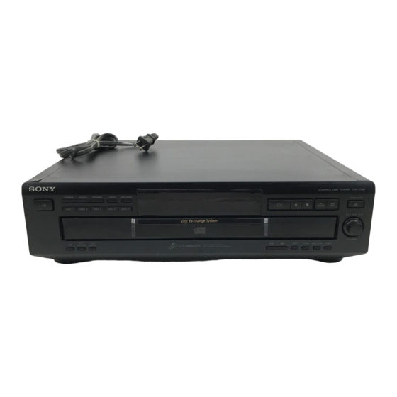
Photo : CDP-CE235
SPECIFICATIONS
Maximum
Load
output
impedance
level
2V
Over 10 kΩ
(at 50 kΩ)
–18 dBm
Wave length:
660 nm
Australian Model
Model Name Using Similar Mechanism
CD Mechanism Type
Base Unit Type
Optical Pick-up Type
General
Power requirements
Where purchased
USA and Canada
Europe and some Asian countries
Other countries
Power consumption
14 W
Dimensions (approx.) 430 × 120 × 385 mm
(17 × 4
× 15
3
(w/h/d)
/
4
Mass (approx.)
5.4 kg (11 lbs 15 oz)
Supplied accessories
Audio cord (2 phono plugs–2 phono plugs) (1)
Remote commander (remote) (1) (CDP-CE335 only)
R6 (size AA) batteries (2) (CDP-CE335 only)
Design and specifications are subject to change without notice.
COMPACT DISC PLAYER
US Model
CDP-C591/CE235/CE335
Canadian Model
AEP Model
UK Model
E Model
CDP-CE235/CE335
NEW
CDM27-5BD32A
BU-5BD32A
KSS-213BA/F-NP
Power requirements
120V AC, 60 Hz
220V – 230V AC, 50/60 Hz
110V – 120V AC or 220V –
240V AC, adjustable, 50/60 Hz
1
/
in.) incl. projecting parts
4
Advertisement
Table of Contents

Related Manuals for Sony CDP-C591


Summary of Contents for Sony CDP-C591
- Page 1 CDP-C591/CE235/CE335 SERVICE MANUAL US Model CDP-C591/CE235/CE335 Canadian Model AEP Model UK Model E Model Australian Model CDP-CE235/CE335 Photo : CDP-CE235 Model Name Using Similar Mechanism CD Mechanism Type CDM27-5BD32A Base Unit Type BU-5BD32A Optical Pick-up Type KSS-213BA/F-NP SPECIFICATIONS Compact Disc Player...
-
Page 2: Table Of Contents
MARK ! ON THE SCHEMATIC DIAGRAMS AND IN THE PARTS CRITIQUES POUR LA SÉCURITÉ DE FONCTIONNEMENT. NE LIST ARE CRITICAL TO SAFE OPERATION. REPLACE THESE REMPLACER CES COMPOSANTS QUE PAR DES PIÈSES SONY COMPONENTS WITH SONY PARTS WHOSE PART NUMBERS DONT LES NUMÉROS SONT DONNÉS DANS CE MANUEL OU APPEAR AS SHOWN IN THIS MANUAL OR IN SUPPLEMENTS DANS LES SUPPÉMENTS PUBLIÉS PAR SONY. - Page 3 4-987- Check the antenna terminals, metal trim, “metallized” knobs, screws, and all other exposed metal parts for AC leakage. Check leakage as described below. CDP-C591 US MODEL : 618-7π LEAKAGE CDP-CE235 US MODEL : 618-0π...
- Page 4 HOW TO OPEN THE DISC TRAY WHEN POWER SWITCH TURNS OFF Insert a tapeing driver into the aperture of the unit bottom, and turn in the direction of arrow (to OUT direction.) * To close the disc tray, turn the driver in the reverse direction(to IN direction).
-
Page 5: General
SECTION 1 GENERAL Identifying the Parts Front Panel 2 3 4 5 6 9 0 !¡ !™ !£ !¢ @¡ !ª !¶ @¢ @™ @º !• !§ !∞ @∞ @£ !¢ 1/u POWER switch 6 OPEN/CLOSE button !∞ CONTINUE button AMS knob !§... -
Page 6: Disassembly
SECTION 2 DISASSEMBLY Note : Follow the disassembly procedure in the numerical order given. 2-1. CASE, BOTTOM PLATE AND FRONT PANEL 4 Case 1 Two screws (M3 × 8) 3 Two screws (BV3 × 8) 2 Two screws 0 Two screws (M3 ×... -
Page 7: Optical Pick-Up Block Assembly
2-3. OPTICAL PICK-UP BLOCK ASSEMBLY 1 Pull out the tray. (Refer to "HOW TO OPEN THE DISC TRAY WHEN 3 Screw POWER SWITCH TURNS OFF" on page 4.) (PTPWH 3 × 12) 4 Two screws 5 Two screws (PTPWH 2.6 × 6) (PTPWH 2.6 ×... -
Page 8: Test Mode
When “8” of the remote controller is pressed, the tracking servo DISCSKIP is turned on. CLOSE Accesses the first program * The servo related items cannot be checked in the CDP-C591/ Playback the first program PLAY display appears CE235/335. OPEN... -
Page 9: Electrical Block Checking
SECTION 4 ELECTRICAL BLOCK CHECKING Note : Clear RF signal waveform means that the shape “ ◊ ” can be clearly Note : Adjustment Location : CD Block is basically designed to operate without adjustment. distinguished at the center of the waveform. Therefore, check each item in order given. -
Page 10: Diagrams
CDP-C591/CE235/CE335 SECTION 5 DIAGRAMS 5-1. CIRCUIT BOARDS LOCATION THIS NOTE IS COMMON FOR PRINTED WIRING BD BOARD BOARDS AND SCHEMATIC DIAGRAMS. (In addition to this necessary note is printed in TABLE MOTOR BOARD each block) Note on Schematic Diagram: Note on Printed Wiring Boards: SENSOR BOARD •... -
Page 11: Ic Block Diagrams
CDP-C591/CE235/CE335 5-2. IC BLOCK DIAGRAMS BD board MAIN board IC601 LA5602 IC101 CXD2587Q IC304 BA6780 V IN ERROR ERROR DIGITAL ASYMMETRY DIGITAL VIN1 VIN2 REFERENCE CORRECTOR CORRECTION VOLTAGE LRCK OPERATIONAL OVER CURRENT AMPLIFIER PCMD FIN1 LIMITTER FIN2 INTERFACE DEMODULATOR ANALOG SWITCH... -
Page 12: Printed Wiring Board - Bd Section
CDP-C591/CE235/CE335 5-3. PRINTED WIRING BOARD – BD SECTION – • See page 10 for Circuit Board Location. (VC) (RF) (PLCK) (GND) (AGCCON) (FE) (TE) (FE1) (Page 14) (TE1) • Semiconductor • Semiconductor Location Location Ref. No. Location Ref. No. Location... -
Page 13: Schematic Diagram - Bd Section
CDP-C591/CE235/CE335 5-4. SCHEMATIC DIAGRAM – BD SECTION – • See page 11 for IC Block Diagrams. • Waveform (Page 15) The components identified by Les composants identifiés par mark ! or dotted line with mark une marque ! sont critiques ! are critical for safety. -
Page 14: Printed Wiring Board - Main Section
CDP-C591/CE235/CE335 5-5. PRINTED WIRING BOARD – MAIN SECTION – • See page 10 for Circuit Board Location. • Semiconductor Location Ref. No. Location D302 D401 D501 D601 D602 D603 D604 D605 D606 D608 D609 IC302 IC304 IC371 G-10 IC401 IC601... -
Page 15: Schematic Diagram - Main Section
CDP-C591/CE235/CE335 5-6. SCHEMATIC DIAGRAM – MAIN SECTION – • See page 11 for IC Block Diagrams. • See page 18 for IC Pin Function. (IC302) • Waveform The components identified by Les composants identifiés par mark ! or dotted line with mark une marque ! sont critiques ! are critical for safety. -
Page 16: Printed Wiring Board - Display Section
CDP-C591/CE235/CE335 5-7. PRINTED WIRING BOARD – DISPLAY SECTION – • See page 10 for Circuit Board Location. — 16 —... -
Page 17: Schematic Diagram - Display Section
CDP-C591/CE235/CE335 5-8. SCHEMATIC DIAGRAM – DISPLAY SECTION – — 17 —... -
Page 18: Ic Pin Function
CDP-C591/CE235/CE335 5-9. IC PIN FUNCTION • IC302 SYSTEM CONTROL (CXP82324-090Q)(MAIN board) Pin No. Pin Name Function Pin No. Pin Name Function BUS IN Not used. (Pull up) FL display tube segmant output 4 RM IN Remote control signal input FL display tube segmant output 5... -
Page 19: Exploded Views
Remarks 4-997-437-11 PANEL, LOADING 4-987-775-01 BUTTON (PLAY) 4-987-779-01 WINDOW (FL)(CE235,C591) 4-987-776-01 BUTTON (FUNC) 4-987-779-11 WINDOW (FL)(CE335) 4-987-774-01 BUTTON (MODE) 3-008-600-01 EMBLEM (5-AR), SONY * 14 1-664-524-11 KEY BOARD 4-987-994-01 KNOB(AMS) 4-999-354-01 BUTTON (POWER) 3-354-981-01 SPRING (SUS), RING * 16 1-664-523-11 P.SW BOARD 4-951-620-01 SCREW (2.6 ×... -
Page 20: Back Panel And Disc Table Section
6-2. BACK PANEL AND DISC TABLE SECTION supplied M801 US,CND MODEL AUS MODEL UK MODEL E MODEL AEP, AED, EA, SP MODEL not supplied not supplied not supplied not supplied Ref. No. Part No. Description Remarks Ref. No. Part No. Description Remarks 4-957-299-11 TABLE (B), DISC... -
Page 21: Chassis Section
6-3. CHASSIS SECTION BU-5BD32A supplied T601 M761 supplied Ref. No. Part No. Description Remarks Ref. No. Part No. Description Remarks 4-957-283-01 WASHER (5), STOPPER * 118 1-659-738-11 LOADING BOARD 4-957-288-01 GEAR (MAIN) X-4949-851-1 PULLEY ASSY 4-957-287-21 GEAR (REV) 4-944-490-01 BELT (TIMING) 4-957-286-11 GEAR (U/D) * 121 4-957-555-01 SHEET, INSULATING(EXCEPT US,CND) -
Page 22: Base Unit Section (Bu-5Bd32A)
6-4. BASE UNIT SECTION (BU-5BD32A) M101 M102 S101 Ref. No. Part No. Description Remarks Ref. No. Part No. Description Remarks ! 751 8-848-379-31 OPTICAL PICK-UP KSS-213BA/F-NP 4-917-564-01 GEAR (P), FLATNESS 1-769-069-11 WIRE (FLAT TYPE) (16 CORE) * 757 A-4724-494-A BD BOARD, COMPLETE 4-951-620-01 SCREW (2.6 ×... -
Page 23: Electrical Parts List
SECTION 7 ELECTRICAL PARTS LIST NOTE: • Due to standardization, replacements in the • CAPACITORS: • SEMICONDUCTORS parts list may be different from the parts uF: µF In each case, u: µ, for example: specified in the diagrams or the components •... - Page 24 DISPLAY LOADING MAIN Ref. No. Part No. Description Remarks Ref. No. Part No. Description Remarks R159 1-216-101-00 METAL CHIP 150K 1/10W < SWITCH > R161 1-216-308-00 METAL CHIP 1/10W R162 1-216-101-00 METAL CHIP 150K 1/10W S801 1-554-303-21 SWITCH, TACTILE(FADER) R171 1-216-078-00 RES,CHIP 1/10W S802...
- Page 25 MAIN Ref. No. Part No. Description Remarks Ref. No. Part No. Description Remarks C509 1-126-163-11 ELECT 4.7uF < COIL > C509 1-126-963-11 ELECT 4.7uF C510 1-162-290-31 CERAMIC 470PF L601 1-412-473-21 INDUCTOR C601 1-119-941-91 ELECT 470uF 6.3V L602 1-414-151-21 INDUCTOR 470uH C602 1-126-944-11 ELECT 3300uF...
- Page 26 MAIN P.SW SENSOR TABLE MOTOR Ref. No. Part No. Description Remarks Ref. No. Part No. Description Remarks R508 1-249-421-11 CARBON 2.2K 1/4W F 1-659-737-11 SENSOR BOARD R509 1-215-405-00 METAL 1/4W ************* R510 1-249-441-11 CARBON 100K 1/4W R512 1-215-405-00 METAL 1/4W <...
- Page 27 Ref. No. Part No. Description Remarks Ref. No. Part No. Description Remarks ACCESSORIES & PACKING MATERIALS ******************************* 1-418-204-11 REMOTE COMMANDER(RM-DC335)(CE335) 1-558-271-11 CORD,CONNECTION(AUDIO) 3-865-901-11 MANUAL, INSTRUCTION(ENGLISH)(US/AUS) 3-865-901-21 MANUAL, INSTRUCTION (ENGLISH/FRENCH/SPANISH)(CND/AEP/E/EA/SP/UK) 3-865-901-31 MANUAL, INSTRUCTION (GERMAN/DUTCH/ITALIAN/PORTUGUESE)(AEP) 3-865-901-41 MANUAL, INSTRUCTION(CHINESE)(E/SP) 3-865-901-51 MANUAL, INSTRUCTION(ARABIC)(EA) 3-865-901-61 MANUAL, INSTRUCTION (SWEDISH/DANISH/FINNISH)(AED) 4-981-643-01 COVER BATTERY (For RM-DC335)(CE335) ************************************************************...
- Page 28 CDP-C591/CE235/CE335 Sony Corporation 99C1689-1 Printed in Japan ©1999.3 Home A&V Products Company 9-928-847-11 Published by Quality Assurance Dept. — 28 — (Shinagawa)
Need help?
Do you have a question about the CDP-C591 and is the answer not in the manual?
Questions and answers