
Related Manuals for Conceptronic CB100S24S


Summary of Contents for Conceptronic CB100S24S
-
Page 1: User Manual
Conceptronic CB100S24S & CB100S48S User Manual ©Copyright 2008. All rights reserved. -
Page 2: Table Of Contents
Safety Instructions ..........................vi Safety Cautions ..........................vi General Precautions for Rack-Mountable Products..................vii Protecting Against Electrostatic Discharge ....................viii Introduction ..........................1 CB100S24S/CB100S48S..........................1 Features ............................1 Ports .............................. 2 Front-Panel Components ........................4 LEDs ............................... 5 Installing the SFP ports ........................6 Installation ..........................7... - Page 3 ENGLISH Port Mirroring ............................25 TFTP Services ............................26 Multiple Image Services .......................... 27 Firmware Information......................... 27 Config Firmware Image ........................27 Forwarding & Filtering ........................... 27 Unicast Forwarding ..........................27 Multicast Forwarding .......................... 28 Multicast Filtering Mode ........................29 L2 Features..........................
-
Page 4: Preface
ENGLISH Preface The CB100S24S/CB100S48S User Manual is divided into sections that describe the system installation and operating instructions with examples. Section 1: Introduction Describes the Switch and its features. Section 2: Installation Helps you get started with the basic installation of the Switch and also describes the front panel, rear panel, side panels, and LED indicators of the Switch. -
Page 5: Intended Readers
ENGLISH Intended Readers The CB100S24S/CB100S48S User Manual contains information for setup and management of the Switch. The term, “the Switch” will be used when referring to both switches. This manual is intended for network managers familiar with network management concepts and terminology. -
Page 6: Safety Instructions
ENGLISH Safety Instructions Use the following safety guidelines to ensure your own personal safety and to help protect your system from potential damage. Throughout this document, the caution icon ( ) is used to indicate cautions and precautions that you need to review and follow. Safety Cautions To reduce the risk of bodily injury, electrical shock, fire, and damage to the equipment, observe the following precautions:... -
Page 7: General Precautions For Rack-Mountable Products
ENGLISH • When connecting or disconnecting power to hot-pluggable power supplies, if offered with your system, observe the following guidelines: Install the power supply before connecting the power cable to the power supply. • Unplug the power cable before removing the power supply. •... -
Page 8: Protecting Against Electrostatic Discharge
ENGLISH Protecting Against Electrostatic Discharge Static electricity can harm delicate components inside your system. To prevent static damage, discharge static electricity from your body before you touch any of the electronic components, such as the microprocessor. You can do so by periodically touching an unpainted metal surface on the chassis. You can also take the following steps to prevent damage from electrostatic discharge (ESD): 1. -
Page 9: Introduction
The following manual describes the installation, maintenance, and configurations concerning the CB100S24S, CB100S48S. These Switches are identical in configuration and very similar in basic hardware and consequentially, most of the information in this manual will be universal to both switches. -
Page 10: Ports
ENGLISH Ports The following table lists the relative ports that are present within each switch as well as the features and compatibility for each port type present in the CB100S24S and CB100S48S: CB100S24S Description Twenty-four 10/100BASE-T Compliant to following standards, IEEE 802.3 compliance... - Page 11 ENGLISH CB100S48S Description Forty-eight Compliant to following standards, 10/100BASE-T IEEE 802.3 compliance IEEE 802.3u compliance Support Half/Full-Duplex operations All ports support Auto MDI-X/MDI-II cross over IEEE 802.3x Flow Control support for Full-Duplex mode, Back Pressure when Half-Duplex mode, and Head-of-line blocking prevention. Two 1000Base- 2 combo 1000BASE-T/SFP ports T/SFP...
-
Page 12: Front-Panel Components
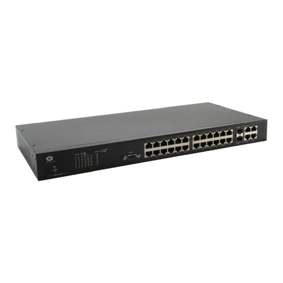
Two 1000BASE-T ports located to the right • One female DCE RS-232 DB-9 console port • LEDs for Power, Console, Link/Act/Speed for each port Figure 1- 1. Front Panel of the CB100S24S CB100S48S • Forty-eight 10/100Mbps BASE-T ports • Two Combo 1000BASE-T/SFP ports located to the right •... -
Page 13: Leds
ENGLISH LEDs The following table lists the LEDs along with their corresponding description: Location LED Indicative Color Status Description Solid Light Power On Power Green Light off Power Off Per Device Solid Light Console on Console Green Blinking POST is in progress/ POST is failure. Light off Console off When there is a secure 100Mbps Fast... -
Page 14: Installing The Sfp Ports
ENGLISH Installing the SFP ports These Switches are equipped with SFP (Small Form Factor Portable) ports, which are to be used with fiber-optical transceiver cabling in order to uplink various other networking devices for a gigabit link that may span great distances. -
Page 15: Installation
Power On • Package Contents Open the shipping carton of the Switch and carefully unpack its contents. The carton should contain the following items: Conceptronic 24/48 Ports 10/100Mbps Smart Switch • AC Power cable • DCE RS-232 console cable •... -
Page 16: Installing The Switch Without The Rack
ENGLISH Installing the Switch without the Rack When installing the Switch on a desktop or shelf, the rubber feet included with the Switch should first be attached. Attach these cushioning feet on the bottom at each corner of the device. Allow enough ventilation space between the Switch and any other objects in the vicinity. -
Page 17: Mounting The Switch In A Standard 19" Rack
ENGLISH Mounting the Switch in a Standard 19" Rack CAUTION: Installing systems in a rack without the front and side stabilizers installed could cause the rack to tip over, potentially resulting in bodily injury under certain circumstances. Therefore, always install the stabilizers before installing components in the rack. After installing components in a rack, do not pull more than one component out of the rack on its slide assemblies at one time. -
Page 18: Connecting The Switch
ENGLISH Section 3 Connecting the Switch Switch to End Node • Switch to Hub or Switch • Connecting to Network Backbone or Server • NOTE: All 10/100/1000Mbps NWay Ethernet ports can support both MDI-II and MDI-X connections. Switch to End Node End nodes include PCs outfitted with a 10, 100 or 1000 Mbps RJ 45 Ethernet/Fast Ethernet Network Interface Card (NIC) and most routers. -
Page 19: Switch To Hub Or Switch
ENGLISH Switch to Hub or Switch These connections can be accomplished in a number of ways using a normal cable. A 10BASE-T hub or switch can be connected to the Switch via a twisted-pair Category 3, 4 or 5 UTP/STP cable. •... -
Page 20: Introduction To Switch Management
ENGLISH Section 4 Introduction to Switch Management Management Options • Web-based Management Interface • Managing User Accounts • Command Line Console Interface through the Serial Port • Connecting the Console Port (RS-232 DCE) • First Time Connecting to the Switch •... - Page 21 ENGLISH 9. After you have correctly set up the terminal, plug the power cable into the power receptacle on the back of the Switch. The boot sequence appears in the terminal. 10. After the boot sequence completes, the console login screen displays. 11.
-
Page 22: First Time Connecting To The Switch
ENGLISH First Time Connecting to the Switch The Switch supports user-based security that can allow you to prevent unauthorized users from accessing the Switch or changing its settings. This section tells how to log onto the Switch. NOTE: The passwords used to access the Switch are case-sensitive; therefore, "S" is not the same as "s."... -
Page 23: Web-Based Switch Configuration
ENGLISH Section 5 Web-based Switch Configuration Introduction • Login to Web manager • Web-Based User Interface • Basic Setup • Reboot • Basic Switch Setup • Network Management • Switch Utilities • Network Monitoring • IGMP Snooping Status • Introduction All software functions of the Switch can be managed, configured and monitored via the embedded web-based (HTML) interface. -
Page 24: Web-Based User Interface
ENGLISH Web-based User Interface The user interface provides access to various Switch configuration and management windows, allows you to view performance statistics, and permits you to graphically monitor the system status. Areas of the User Interface The figure below shows the user interface. The user interface is divided into three distinct areas as described in the table. -
Page 25: Web Pages
ENGLISH NOTICE: Any changes made to the Switch configuration during the current session must be saved in the Save Changes web menu (explained below). Web Pages When you connect to the management mode of the Switch with a web browser, a login window is displayed. Enter a user name and password to access the Switch's management mode. -
Page 26: Administration
ENGLISH Section 6 Administration IP Address • Port Configuration • User Accounts • Port Mirroring • TFTP Services • Multiple Image Services • Forwarding & Filtering • Device Information This window contains the main settings for all major functions for the Switch and appears automatically when you log on. -
Page 27: Ip Address
ENGLISH IGMP Snooping To enable system-wide IGMP Snooping capability select Enabled. IGMP snooping is Disabled by default. Enabling IGMP snooping allows you to specify use of a multicast router only (see below). To configure IGMP Snooping for individual VLANs, use the IGMP Snooping window located in the IGMP Snooping folder contained in the L2 Features folder. -
Page 28: Port Configuration
ENGLISH NOTE: The Switch's factory default IP address is 192.168.0.200 with a subnet mask of 255.255.255.0 and a default gateway of 192.168.0.1. To use the BOOTP or DHCP protocols to assign the Switch an IP address, subnet mask, and default gateway address: Use the Get IP From pull-down menu to choose from BOOTP or DHCP. -
Page 29: Port Settings
ENGLISH Port Settings Click Administration > Port Configuration > Port Settings to display the following window: To configure switch ports: 1. Choose the port or sequential range of ports using the From…To… port pull-down menus. Use the remaining pull-down menus to configure the parameters described below: Figure 6- 3. -
Page 30: Port Description
ENGLISH The following parameters can be configured: Parameter Description From…. To Use the pull-down menus to select the port or range of ports to be configured. State Toggle this field to either enable or disable a given port or group of ports. Speed/Duplex Toggle the Speed/Duplex field to either select the speed and duplex/half-duplex state of the port. - Page 31 ENGLISH Figure 6- 4. Port Description window...
-
Page 32: User Accounts
ENGLISH User Accounts Use the User Account Management window to control user privileges. To view existing User Accounts, open the Administration folder and click on the User Accounts link. This will open the User Account Management window, as shown below. Figure 6- 5. -
Page 33: Port Mirroring
ENGLISH Port Mirroring The Switch allows you to copy frames transmitted and received on a port and redirect the copies to another port. You can attach a monitoring device to the mirrored port, such as a sniffer or an RMON probe, to view details about the packets passing through the first port. -
Page 34: Tftp Services
ENGLISH TFTP Services Trivial File Transfer Protocol (TFTP) services allow the Switch's firmware to be upgraded by transferring a new firmware file from a TFTP server to the Switch. A configuration file can also be loaded into the Switch from a TFTP server. -
Page 35: Multiple Image Services
ENGLISH Multiple Image Services To configure the files located on the Flash memory, use the following windows to guide you. Firmware Information This window is used to view boot up firmware images. Figure 6- 10. Firmware Information window Config Firmware Image The following window is used to determine which of the two firmware images will be used as the default boot file. -
Page 36: Multicast Forwarding
ENGLISH To add or edit an entry, define the following parameters and then click Add/Modify: Parameter Description The VLAN ID number of the VLAN on which the above Unicast MAC address resides. MAC Address The MAC address to which packets will be statically forwarded. This must be a unicast MAC address. -
Page 37: Multicast Filtering Mode
ENGLISH The following parameters can be set: Parameter Description The VLAN ID of the VLAN to which the corresponding MAC address belongs. Multicast MAC The MAC address of the static source of multicast packets. This must be a multicast MAC Address address. -
Page 38: L2 Features
ENGLISH Section 7 L2 Features VLAN • Trunking • IGMP Snooping • Spanning Tree • VLANs A Virtual Local Area Network (VLAN) is a network topology configured according to a logical scheme rather than the physical layout. VLANs can be used to combine any collection of LAN segments into an autonomous user group that appears as a single LAN. -
Page 39: Q Vlan Tags
ENGLISH VLANs to span multiple 802.1Q-compliant switches through a single physical connection and allows Spanning Tree to be enabled on all ports and work normally. The IEEE 802.1Q standard restricts the forwarding of untagged packets to the VLAN of which the receiving port is a member. -
Page 40: Tagging And Untagging
ENGLISH Figure 7- 2. IEEE 802.1Q Tag The EtherType and VLAN ID are inserted after the MAC source address, but before the original EtherType/Length or Logical Link Control. Because the packet is now a bit longer than it was originally, the Cyclic Redundancy Check (CRC) must be recalculated. -
Page 41: Default Vlans
ENGLISH dropped. If the destination port is a member of the 802.1Q VLAN, the packet is forwarded and the destination port transmits it to its attached network segment. If the packet is not tagged with VLAN information, the ingress port will tag the packet with its own PVID as a VID (if the port is a tagging port). -
Page 42: Static Vlan Entry
ENGLISH Static VLAN Entry In the L2 Features folder, open the VLAN folder and click the Static VLAN Entry link to open the following window: Figure 7- 4. Static VLANs Entry Settings window The 802.1Q Static VLANs window lists all previously configured VLANs by VLAN ID and VLAN Name. To delete an existing 802.1Q VLAN, click the corresponding button under the Delete heading. - Page 43 ENGLISH Figure 7- 6. 802.1Q Static VLANs window - Modify The following fields can then be set in either the Add or Modify 802.1Q Static VLANs windows: Parameter Description Allows the entry of a VLAN ID in the Add dialog box, or displays the VLAN ID of an existing VLAN in the Modify dialog box.
-
Page 44: Trunking
ENGLISH Trunking Port trunk groups are used to combine a number of ports together to make a single high-bandwidth data pipeline. The Switch supports up to six port trunk groups with 2 to 8 ports in each group. A potential bit rate of 800 Mbps can be achieved. -
Page 45: Link Aggregation
ENGLISH Load balancing is automatically applied to the ports in the aggregated group, and a link failure within the group causes the network traffic to be directed to the remaining links in the group. The Spanning Tree Protocol will treat a link aggregation group as a single link, on the switch level. On the port level, the STP will use the port parameters of the Master Port in the calculation of port cost and in determining the state of the link aggregation group. -
Page 46: Igmp Snooping
ENGLISH IGMP Snooping Internet Group Management Protocol (IGMP) snooping allows the Switch to recognize IGMP queries and reports sent between network stations or devices and an IGMP host. When enabled for IGMP snooping, the Switch can open or close a port to a specific device based on IGMP messages passing through the Switch. In order to use IGMP Snooping it must first be enabled for the entire Switch (see Device Information). - Page 47 ENGLISH The following parameters may be viewed or modified: Parameter Description VLAN ID This is the VLAN ID that, along with the VLAN Name, identifies the VLAN for which to modify the IGMP Snooping Settings. VLAN Name This is the VLAN Name that, along with the VLAN ID, identifies the VLAN for which to modify the IGMP Snooping Settings.
-
Page 48: Static Router Ports Settings
ENGLISH Static Router Ports Settings A static router port is a port that has a multicast router attached to it. Generally, this router would have a connection to a WAN or to the Internet. Establishing a router port will allow multicast packets coming from the router to be propagated through the network, as well as allowing multicast messages (IGMP) coming from the network to be propagated to the router. -
Page 49: Spanning Tree
ENGLISH Click Apply to implement the new settings, Click the Show All Static Router Port Entries link to return to the Current Static Router Port Entries window. Spanning Tree 802.1w Rapid Spanning Tree The Switch implements the Rapid Spanning Tree Protocol (RSTP) as defined by the IEEE 802.1w specification and a version compatible with the IEEE 802.1d STP. -
Page 50: P2P Port
ENGLISH P2P Port A P2P port is also capable of rapid transition. P2P ports may be used to connect to other bridges. Under RSTP, all ports operating in full-duplex mode are considered to be P2P ports, unless manually overridden through configuration. -
Page 51: Stp Bridge Global Settings
ENGLISH STP Bridge Global Settings To open the following window, open Spanning Tree in the L2 features folder and click the STP Bridge Global Settings link. Figure 7- 14. STP Bridge Global Settings window The following parameters can be set: Parameter Description Spanning Tree Protocol... - Page 52 ENGLISH STP Version Use the pull-down menu to choose the desired version of STP to be implemented on the Switch. There are two choices: STPCompatability - Select this parameter to set the Spanning Tree Protocol (STP) globally on the switch. RSTP - Select this parameter to set the Rapid Spanning Tree Protocol (RSTP) globally on the Switch.
-
Page 53: Stp Port Settings
ENGLISH STP Port Settings STP can be set up on a port per port basis. To view the following window click L2 Features > Spanning Tree > STP Port Settings: Figure 7- 15. STP Port Settings window In addition to setting Spanning Tree parameters for use on the switch level, the Switch allows for the configuration of groups of ports, each port-group of which will have its own spanning tree, and will require some of its own configuration settings. - Page 54 ENGLISH An STP Group spanning tree works in the same way as the switch-level spanning tree, but the root bridge concept is replaced with a root port concept. A root port is a port of the group that is elected based on port priority and port cost, to be the connection to the network for the group.
-
Page 55: Cos
ENGLISH Section 8 802.1p Default Priority • 802.1p User Priority • The Switch supports 802.1p priority queuing Quality of Service. The following section discusses the implementation of CoS (Quality of Service) and benefits of using 802.1p priority queuing. Understanding IEEE 802.1p Priority Priority tagging is a function defined by the IEEE 802.1p standard designed to provide a means of managing traffic on a network where many different types of data may be transmitted simultaneously. - Page 56 ENGLISH Advantages of CoS CoS is an implementation of the IEEE 802.1p standard that allows network administrators a method of reserving bandwidth for important functions that require a large bandwidth or have a high priority, such as VoIP (voice-over Internet Protocol), web browsing applications, file server applications or video conferencing. Not only can a larger bandwidth be created, but other less critical traffic can be limited, so excessive bandwidth can be saved.
-
Page 57: Understanding Cos
ENGLISH Understanding CoS The Switch has four priority classes of service. These priority classes of service are labeled as 3, the high class to 0, the lowest class. The eight priority tags, specified in IEEE 802.1p are mapped to the Switch's priority classes of service as follows: Priority 0 is assigned to the Switch's Q1 class. -
Page 58: 802.1P Default Priority
ENGLISH 802.1p Default Priority The Switch allows the assignment of a default 802.1p priority to each port on the Switch. In the CoS folder, click 802.1p Default Priority, to view the window shown below. Figure 8- 2. 802.1p Default Priority window This window allows you to assign a default 802.1p priority to any given port on the Switch. -
Page 59: 802.1P User Priority
ENGLISH 802.1p User Priority When using 802.1p priority mechanism, the packet is examined for the presence of a valid 802.1p priority tag. If the tag is present, the packet is assigned to a programmable egress queue based on the value of the tagged priority. -
Page 60: Security
ENGLISH Section 9 Security 802.1X • 802.1X 802.1x Port-Based and MAC-Based Access Control The IEEE 802.1x standard is a security measure for authorizing and authenticating users to gain access to various wired or wireless devices on a specified Local Area Network by using a Client and Server based access control model. -
Page 61: Authentication Server
ENGLISH Authentication Server The Authentication Server is a remote device that is connected to the same network as the Client and Authenticator, must be running a RADIUS Server program and must be configured properly on the Authenticator (Switch). Clients connected to a port on the Switch must be authenticated by the Authentication Server (RADIUS) before attaining any services offered by the Switch on the LAN. -
Page 62: Authentication Process
ENGLISH Client The Client is simply the endstation that wishes to gain access to the LAN or switch services. All endstations must be running software that is compliant with the 802.1x protocol. For users running Windows XP, that software is included within the operating system. - Page 63 ENGLISH Understanding 802.1x Port-based and MAC-based Network Access Control The original intent behind the development of 802.1x was to leverage the characteristics of point-to-point in LANs. As any single LAN segment in such infrastructures has no more than two devices attached to it, one of which is a Bridge Port.
- Page 64 ENGLISH MAC-Based Network Access Control RADIUS Server Ethernet Switch … 802.1X 802.1X 802.1X 802.1X 802.1X 802.1X 802.1X 802.1X 802.1X 802.1X 802.1X 802.1X Client Client Client Client Client Client Client Client Client Client Client Client Network access controlled port Network access uncontrolled port Figure 9- 8.
-
Page 65: 802.1X Authenticator Settings
ENGLISH 802.1x Authenticator Settings To configure the 802.1X Authenticator Settings, click Security > 802.1X > 802.1X Authenticator Settings: Figure 9- 9. 802.1x Authenticator Settings window... - Page 66 ENGLISH To configure the settings by port, click on its corresponding Ports link, which will display the following table to configure: Figure 9- 10. 802.1X Authenticator Settings window (Modify) This window allows users to set the following features: Parameter Description From/To] Enter the port or ports to be set.
- Page 67 ENGLISH QuietPeriod This allows you to set the number of seconds that the Switch remains in the “Held” state following a failed authentication exchange with the client. The default setting is 60 seconds. SuppTimeout This value determines timeout conditions in the exchanges between the Authenticator and the client.
-
Page 68: Local Users
ENGLISH Local Users In the Security folder, open the 802.1x folder and click 802.1X User to open the 802.1x User window. This window will allow the user to set different local users on the Switch. Figure 9- 11. Local Users Configuration window Enter a User Name, Password and confirmation of that password. -
Page 69: X Capability Settings
ENGLISH 802.1X Capability Settings In the Security folder, open the 802.1x folder and click 802.1X Capability Settings to open the 802.1x Capability Settings window. This window will allow the user to set capability settings for each port on the Switch. Figure 9- 12. - Page 70 ENGLISH This window displays the following information: Parameter Description From and To Select the port or range of ports to be set. Capability This allows the 802.1x Authenticator settings to be applied on a per-port basis. Select Authenticator to apply the settings to the port. When the setting is activated A user must pass the authentication process to gain access to the network.
-
Page 71: Radius Server
ENGLISH RADIUS Server The RADIUS feature of the Switch allows you to facilitate centralized user administration as well as providing protection against a sniffing, active hacker. The Web Manager offers three windows. Click Security > 802.1x > RADIUS Server to open the RADIUS Server window shown below: Figure 9- 13. -
Page 72: Monitoring
ENGLISH Section 10 Monitoring MAC Address • IGMP Snooping Group • Browse Router Port • Port Access Control • MAC Address This allows the Switch's dynamic MAC address forwarding table to be viewed. When the Switch learns an association between a MAC address and a port number, it makes an entry into its forwarding table. These entries are then used to forward packets through the Switch. - Page 73 ENGLISH The following fields can be viewed or set: Parameter Description VLAN Name Enter a VLAN Name by which to browse the forwarding table. MAC Address Enter a MAC address by which to browse the forwarding table. Port Select the port by using the corresponding pull-down menu. Find Allows the user to move to a sector of the database corresponding to a user defined port, VLAN, or MAC address.
-
Page 74: Igmp Snooping Group
ENGLISH IGMP Snooping Group This window allows the Switch’s IGMP Snooping Group Table to be viewed. IGMP Snooping allows the Switch to read the Multicast Group IP address and the corresponding MAC address from IGMP packets that pass through the Switch. The number of IGMP reports that were snooped is displayed in the Reports field. -
Page 75: Browse Router Port
ENGLISH Browse Router Port This displays which of the Switch’s ports are currently configured as router ports. A router port configured by a user (using the Web-based management interfaces) is displayed as a static router port, designated by S. A router port that is dynamically configured by the Switch is designated by D. - Page 76 ENGLISH The following fields can be viewed: Parameter Description ServerIndex The identification number assigned to each RADIUS Authentication server that the client shares a secret with. ServerIPaddr The identification IP address of the server. UDP Port The UDP port the client is using to send requests to this server. Timeouts The number of authentication timeouts to this server.
-
Page 77: Auth State
ENGLISH Auth State Auth State is unable to be viewed unless the Switch is set to Port-based or MAC-based for the 802.1X function. This table displays the Authenticator State for each port. To view the Authenticator State, click Monitoring > Port Access Control >... -
Page 78: Reset
ENGLISH Reset The Reset function has several options when resetting the Switch. Some of the current configuration parameters can be retained while resetting all other configuration parameters to their factory defaults. NOTE: Only the Reset System option will enter the factory default parameters into the Switch’s non-volatile RAM, and then restart the Switch. -
Page 79: Reboot System
ENGLISH Reboot System The following window is used to restart the Switch. Figure 10- 7. Reboot System window Clicking the Yes radio button will instruct the Switch to save the current configuration to non-volatile RAM before restarting the Switch. Clicking the No radio button instructs the Switch not to save the current configuration before restarting the Switch. All of the configuration information entered from the last time Save Changes was executed, will be lost. -
Page 80: Logout
ENGLISH Logout Click the Logout button on the Logout window to immediately exit the Switch. Figure 10- 9. Logout window... -
Page 81: Technical Specifications
UTP Cat.5, Cat. 5 Enhanced for 100BASE-TX UTP Cat.3, 4, 5 for 10BASE-T EIA/TIA-568 100-ohm screened twisted-pair (STP)(100m) Number of Ports CB100S24S: 24 x 10/100Base-T Ports 2 x 1000Base-T/SFP Combo Ports 2 x 1000Base-T ports CB100S48S: 48 x 10/100Base-T Ports... - Page 82 Humidity 5 - 95% non-condensing Dimensions 19” Metal Case 441(W) x 207(D) x 44(H) mm, 1U Rack-Mount size (CB100S24S) 441(W) x 309(D) x 44(H) mm, 1U Rack-Mount size (CB100S48S) CE Class A, FCC Class A, C-Tick, VCCI Safety CB Report, UL...
- Page 83 Store and Forward Switching Capacity 12.8Gbps for CB100S24S 17.6Gbps for CB100S48S 64 Byte system packet forwarding 9.5 million packets per second for CB100S24S rate 13.1 million packets per second for CB100S48S Priority Queues 4 Priority Queues per port MAC Address Table...
- Page 84 ENGLISH Port Functions Feature Detailed Description DCE RS-232 DB-9 for loading factory reset purpose Console Port Compliant to following standards, 1. IEEE 802.3 compliance 24 x 10/100BaseT ports 2. IEEE 802.3u compliance 48 x 10/100BaseT ports 3. Support Half/Full-Duplex operations 4.
-
Page 85: System Log Entries
ENGLISH Appendix B System Log Entries The following table lists all possible entries and their corresponding meanings that will appear in the System Log of this Switch. Category Event Description Log Content Severity system System started up Uint <unitID>, System started up Critical Configuration saved to flash Uint <unitID>, Configuration saved to flash... - Page 86 ENGLISH Category Event Description Log Content Severity Port link down Port <unitID:portNum> link down Informational Console Successful login through Console Unit <unitID>, Successful login through Informational Console (Username: <username>) Login failed through Console Unit <unitID>, Login failed through Console Warning (Username: <username>) Logout through Console Unit <unitID>, Logout through Console...
- Page 87 ENGLISH Category Event Description Log Content Severity SNMP SNMP request received with SNMP request received from <ipAddress> Informational invalid community string with invalid community string! Topology changed Topology changed Informational New Root selected New Root selected Informational BPDU Loop Back on port BPDU Loop Back on Port <unitID:portNum>...
- Page 88 ENGLISH Category Event Description Log Content Severity Login failed through Web Login failed failed through Web from Warning authenticated by AAA local <userIP> authenticated by AAA local method method (Username: <username>, MAC: <macaddr>) Successful login through Successful login through Web(SSL) from Informational Web(SSL) authenticated by AAA <userIP>...
- Page 89 ENGLISH Category Event Description Log Content Severity Successful login through Telnet Successful login through Telnet from Informational authenticated by AAA none <userIP> authenticated by AAA none method method (Username: <username>, MAC: <macaddr>) Successful login through SSH Successful login through SSH from <userIP> Informational authenticated by AAA none authenticated by AAA none method...
- Page 90 ENGLISH Category Event Description Log Content Severity Successful Enable Admin through Successful Enable Admin through Console Informational Console authenticated by AAA authenticated by AAA local_enable method local_enable method (Username: <username>) Enable Admin failed through Enable Admin failed through Console Warning Console authenticated by AAA authenticated by AAA local_enable method local_enable method...
- Page 91 ENGLISH Category Event Description Log Content Severity Successful Enable Admin through Successful Enable Admin through SSH from Informational SSH authenticated by AAA none <userIP> authenticated by AAA none method method (Username: <username>, MAC: <macaddr>) Successful Enable Admin through Successful Enable Admin through Console Informational Console authenticated by AAA authenticated by AAA server <serverIP>...
- Page 92 ENGLISH Category Event Description Log Content Severity Safeguard Engine is in filtering Safeguard Engine enters EXHAUSTED mode Warning packet mode Packet Storm Port <unitID:portNum> Broadcast storm is Broadcast strom occurrence Warning occurring Port <unitID:portNum> Broadcast storm Broadcast storm cleared Informational has cleared Port <unitID:portNum>...
-
Page 93: Cable Lengths
ENGLISH Appendix C Cable Lengths Use the following table to as a guide for the maximum cable lengths. Standard Media Type Maximum Distance Mini-GBIC 1000BASE-LX, Single-mode fiber module 10km 1000BASE-SX, Multi-mode fiber module 550m 1000BASE-LHX, Single-mode fiber module 40km 1000BASE-ZX, Single-mode fiber module 80km 1000BASE-T Category 5e UTP Cable... -
Page 94: Glossary
Appendix D Glossary 1000BASE-SX: A short laser wavelength on multimode fiber optic cable for a maximum length of 2000 meters 1000BASE-LX: A long wavelength for a "long haul" fiber optic cable for a maximum length of 10 kilometers 100BASE-FX: 100Mbps Ethernet implementation over fiber. 100BASE-TX: 100Mbps Ethernet implementation over Category 5 and Type 1 Twisted Pair cabling. - Page 95 Fast Ethernet: 100Mbps technology based on the Ethernet/CMSA/CD network access method. Flow Control: (IEEE 802.3z) A means of holding packets back at the transmit port of the connected end station. Prevents packet loss at a congested switch port. Forwarding: The process of sending a packet toward its destination by an internetworking device. Full duplex: A system that allows packets to be transmitted and received at the same time and, in effect, doubles the potential throughput of a link.
- Page 96 Server farm: A cluster of servers in a centralized location serving a large user population. SLIP: Serial Line Internet Protocol: A protocol, which allows IP to run over a serial line connection. SNMP: Simple Network Management Protocol: A protocol originally designed to be used in managing TCP/IP internets.
Need help?
Do you have a question about the CB100S24S and is the answer not in the manual?
Questions and answers