
Summary of Contents for VAL Avionics NAV 2000
- Page 1 VAL AVIONICS LTD NAV 2000 ULTRA-THIN NAVIGATION RECEIVER Installation and Operator’s Manual Release Issue Oct. 2013 P/N 172203-0...
- Page 2 V A L A V I O N I C S L T D N A V 2 0 0 0 N A V I G A T I O N R E C E I V E R I N S T A L L A T I O N A N D O P E R A T O R ’...
-
Page 3: Table Of Contents
Figure 3: Panel Cut Out ..............................15 Figure 4: Mounting Tray Assembly Exploded View ..................... 15 Figure 5: NAV 2000 Basic Wiring Diagram........................17 Figure 6: NAV 2000 to Nav Indicator ..........................17 ......................17 Figure 7: NAV 2000 to Nav Converter... -
Page 4: Section I - General Information
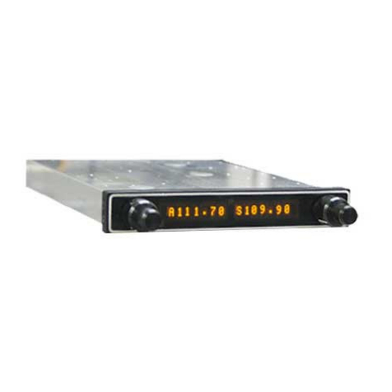
1.3 EQUIPMENT DESCRIPTION The NAV 2000 has been designed for simplicity. It is straight forward to install and operate. Using state of the art technology Val Avionics Ltd. has created a navigation receiver that will provide the pilot with simple, easy to interpret navigation information for in-route VOR navigation and ILS Approaches. -
Page 5: Specifications
CDI Glide slope Flag 250mv into 1K Load CDI VOR/LOC Flag 250mv into 1K Load Composite Output 500mv into 1K Load Manufacturer’s Model Number NAV 2000 Part Number VPN 0800120-1 FCC ID EZNNAV2000 Release issue Page 5 of 29 Oct. 2013... -
Page 6: Equipment Supplied
O P E R A T O R ’ S M A N U A L 1.5 EQUIPMENT SUPPLIED Table 2: Equipment Supplied PART NUMBER DESCRIPTION 0800120 NAV 2000 NAVIGATION SYSTEM INSTALLATION KIT 0651020 1.6 EQUIPMENT REQUIRED BUT NOT SUPPLIED Table 3: Equipment Not Supplied DESCRIPTION... -
Page 7: Section Ii - Installation
Although the NAV 2000 installation procedures are designed with the do-it-yourself in mind, we at Val Avionics Ltd. strongly suggest that you seek the advice of a qualified avionics installation facility before beginning this or any other installation project. Qualified avionics installation technicians can offer good advice as to time-tested installation practices and techniques that can save you many hours of time and frustration. -
Page 8: Wire Harness Fabrication
Although strongly recommended, it is not required to use the factory fabricated wire harness when installing the NAV 2000. A wiring harness can be fabricated in the field. Refer to appendix B of this manual for a complete wiring diagram. The NAV 2000 is connected to the aircrafts avionics bus via a 2 AMP circuit breaker. -
Page 9: Post Installation Check
Audio 2.3.4.3 The NAV 2000 has one navigation audio output. Although the audio output levels of the receivers are capable of driving a standard headset directly, it is strongly recommended that these audios be coupled to a quality audio selector panel. For complete details, refer to the interconnect wiring diagrams in Appendix B. -
Page 10: Section Iii - Operation
3 SECTION III - OPERATION 3.1 GENERAL INFORMATION 3.1.1 Scope This section will provide detailed operating instructions for your new NAV 2000 Navigation Receiver. Please read this section completely to become familiar with all of the features of the unit. 3.1.2 Display Functions 3.1.3 User Controls... -
Page 11: System Configuration
V A L A V I O N I C S L T D N A V 2 0 0 0 N A V I G A T I O N R E C E I V E R I N S T A L L A T I O N A N D O P E R A T O R ’... - Page 12 • If there is an error, the display will show “Err” • If the result of “Err” is received, check your wiring between the mechanical resolver and the NAV 2000 Serial Mode (SrMd) 3.2.1.4 The serial mode configures the RS-232 output to work either as a standalone navigation unit (DIR), or as a slave to the COM 2000 to fully emulate the SL-30 (PAS).
-
Page 13: Section Iv - Warranty And Service
In such cases, an estimate will be submitted for approval before repair is initiated. In most cases, Val avionics, Ltd. will provide 72-hour turn around on its warranty and repair service. We recommend that contact be made with the FACTORY CUSTOMER SERVICE DEPARTMENT prior to any unit return and obtain RETURN AUTHORIZATION AND INSTRUCTIONS. -
Page 14: Appendix A - Installation Drawings And Connector Layout
V A L A V I O N I C S L T D N A V 2 0 0 0 N A V I G A T I O N R E C E I V E R I N S T A L L A T I O N A N D O P E R A T O R ’... - Page 15 V A L A V I O N I C S L T D N A V 2 0 0 0 N A V I G A T I O N R E C E I V E R I N S T A L L A T I O N A N D O P E R A T O R ’...
- Page 16 V A L A V I O N I C S L T D N A V 2 0 0 0 N A V I G A T I O N R E C E I V E R I N S T A L L A T I O N A N D O P E R A T O R ’...
-
Page 17: Appendix B - Wiring Diagrams
O P E R A T O R ’ S M A N U A L 6 Appendix B – WIRING DIAGRAMS Figure 5: NAV 2000 Basic Wiring Diagram Figure 6: NAV 2000 to Nav Indicator Figure 7: NAV 2000 to Nav Converter... - Page 18 V A L A V I O N I C S L T D N A V 2 0 0 0 N A V I G A T I O N R E C E I V E R I N S T A L L A T I O N A N D O P E R A T O R ’...
-
Page 19: Appendix C - Instructions For Continued Airworthiness
AIRWORTHINESS 7.1 MAINTENANCE INSTRUCTIONS Maintenance of the NAV 2000 Navigation Receiver is on condition only. No periodic maintenance is required. VOR calibration, in accordance with 14 CFR 91.171, is required to be checked every 30 days. If unit is found to be out of calibration, send unit in for service. If the unit is removed for service, upon re-... -
Page 20: Appendix D - Rs-232 Instruction Listing
• 8.4 Default Message Output At system start when the NAV 2000 is configured to operate in normal mode, the following messages will be configured for output and the specified rates: CDI, VDI, and Flags at 10 Hz (high rate) •... -
Page 21: Message Formats
COMM of VHF NAV message. Those message types, which are also supported by the VAL COM 2000 VHF Transceiver, will use the “C” identifier to allow the NAV 2000 to accept COMM radio commands from existing products. All other messages will use the “V” identifier to indicate that they relate to a VHF NAV receiver. -
Page 22: Message Definitions
This message is used to set the standby VOR or Localizer frequency as well as the receiver operating function. The NAV 2000 can detect if the supplied frequency corresponds to a VOR or a Localizer channel, so this command will work for both types of NAV aids. - Page 23 This message is used to set the standby VOR or Localizer frequency as well as the receiver operating function. The NAV 2000 can detect if the supplied frequency corresponds to a VOR or a Localizer channel, so this command will work for both types of NAV aids.
- Page 24 SET NAV OMNI-BEARING SELECT (OBS) VALUE This message is used to set the OBS value used by the NAV 2000 as the elected radial for computing the course deviation from a VOR. This message will have no effect unless the NAV 2000 is configured to use the internal OBS source, or a serial OBS source.
- Page 25 V A L A V I O N I C S L T D N A V 2 0 0 0 N A V I G A T I O N S Y S T E M I N S T A L L A T I O N A N D O P E R A T O R ’...
- Page 26 OUTPUT MESSAGES RESET STATUS This message is sent to indicate to the host that the NAV 2000 is running and ready to accept data on the serial port. It will be sent once upon startup and when requested by the host.
- Page 27 V A L A V I O N I C S L T D N A V 2 0 0 0 N A V I G A T I O N S Y S T E M I N S T A L L A T I O N A N D O P E R A T O R ’...
- Page 28 V A L A V I O N I C S L T D N A V 2 0 0 0 N A V I G A T I O N S Y S T E M I N S T A L L A T I O N A N D O P E R A T O R ’...
- Page 29 V A L A V I O N I C S L T D N A V 2 0 0 0 N A V I G A T I O N S Y S T E M I N S T A L L A T I O N A N D O P E R A T O R ’...
Need help?
Do you have a question about the NAV 2000 and is the answer not in the manual?
Questions and answers