Table of Contents

Related Manuals for Vishay 2310B

Summary of Contents for Vishay 2310B
-
Page 1: Signal Conditioning Amplifier
2300 SYSTEM Signal Conditioning Amplifier 2310B Instruction Manual Vishay Micro-Measurements P.O. Box 27777 Raleigh, NC 27611 United States Telephone +1-919-365-3800 FAX +1-919-365-3945 E-mail: vmm.us@vishaymg.com www.vishaymg.com Oct 2009 130-000137... -
Page 2: Table Of Contents
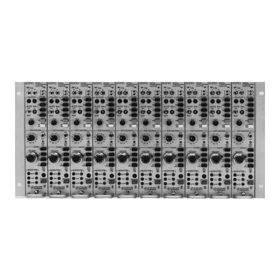
STANDARD CALIBRATION RESISTORS ....................18 6.0 ACTIVE FILTER ................................. 19 FILTER CHARACTERISTICS ........................19 7.0 MAINTENANCE................................20 ADJUSTMENTS............................... 20 BATTERY REPLACEMENT.......................... 22 COMPONENT REPLACEMENT........................22 FUSE REPLACEMENT........................... 23 APPENDIX.................................... 23 WARRANTY ..................................24 © Copyright Vishay Micro-Measurements, 1995-2009 All Rights Reserved. - Page 3 Complete 10-Channel 2300 System 4-channel System in 2360 Portable Enclosure 2310 Signal Conditioning Amplifier Module with Stabilizer Accessory 2350 10-Channel Rack Adapter - 2 -...
-
Page 4: Description
Eleven settings: 0.7, 1, 1.4, 2, 2.7, 3.5, 5, 7, 10, 12 and 15 Vdc ±1% max. One variable setting : 0.2 to The Model 2350 Rack Adapter accepts up to ten 2310B 7 Vdc Amplifiers for mounting in a standard 19-in (483-mm) rack;... -
Page 5: 2350 Rack Adapter
FILTER: 13.5 lb (6.1 kg). Characteristic: Low-pass active six-pole Butterworth standard. 2.3 2360 PORTABLE ENCLOSURE Frequencies (-3 ±1 dB): 10, 100, 1000 and 10 000 DESCRIPTION: Hz and wide-band. Enclosure to accept up to four 2310B Amplifiers. - 4 -... -
Page 6: Controls
The operating procedure is 115 or 230 Vac switch selected in amplifiers, 50/60 covered in Section 4.0. Hz, 40 Watts max. 3.1 2310B FRONT PANEL SIZE & WEIGHT: CAL Switches: Toggle switches to place shunt- 9.06 H x 7.20 W x 18.90 D in calibration resistors across arms of the input bridge. -
Page 7: 2310 Rear Panel
±1.414V (1 Vrms for sine waves). INPUT Receptacle: A 15-pin quarter-turn connector to connect the input circuit to the 2310B. Quarter, half, and full bridges, potentiometers, or voltage inputs can be accepted simply by using the appropriate pins; see 4.2 Gage Input Connections for details. -
Page 8: Operating Procedure
4.2 GAGE INPUT CONNECTIONS recommended; neither of these circuits requires It is suggested that the 2310B be turned on (press the red additional wiring from that shown in Figure 2. POWER button) and allowed to stabilize while... -
Page 9: Millivolt Inputs
(and insulated against accidental groundings) at the gage end. The 2310B Amplifier can accept dc inputs, such as Normally the guard shield is used inside a conventionally thermocouples, provided two requirements are observed: grounded shield, as shown in Figure 2C. -
Page 10: Output Connections
The 2310B Amplifier has two simultaneous non- interacting outputs; any one or all may be used in a particular test. Both outputs are accessible at the rear of the 2310B utilizing coaxial (BNC) connectors. -
Page 11: Filter Output Selector
To select the outputs to be filtered, open the right side- semifloating. Unless some ground exists in the input cover of the 2310B and note the two toggles on the red circuit, the supply automatically centers itself about FILTER switch (near the top of the p.c. board) marked circuit common (e.g., when set at 5B, P+ will read... -
Page 12: Amplifier Balance
POWER is turned off (or there is a failure in the ac RESET position, and release. In 1 to 3 seconds (8 mains) since the 2310B has a keep-alive supply (a small seconds under the most extreme conditions) the battery) to power this circuit at all times. -
Page 13: Filter
Note that this equation assumes one active gage; 4.13 FILTER additional active gages will increase the output. The standard 2310B is equipped with a 6-pole low-pass Equation 6 can be rearranged as: active filter which, depending on which FILTER button... -
Page 14: Dynamic Testing
To use the playback mode, move the PLAYBACK coupling is selected, there is a maximum permissible switch on the rear panel of the 2310B to ON (up). differential dc input which must not be exceeded (to Connect the output from the tape recorder to the INPUT avoid saturation of the preamplifier);... -
Page 15: Remote-Operation Relays
+15V supply may be used, as shown in Figure be at REMOTE, and 8A. When more than one 2310B is to be operated with a single set of switches (or external relays), an external 5 The EXCITATION selector switch must be set at Vdc power supply is required (250 mA for each 10 half the desired bridge excitation. -
Page 16: Shunt Calibration Components In 2310
+ or -. (If both necessary for the shunting effect of the resistance switches are operated simultaneously the values are balance circuit, since the 2310B does not use the shunt algebraically additive.) method for bridge balance.) With Option Y additional relays are installed in the Gage factor (K´) in equation 10 may be the actual... -
Page 17: Transducers
CKT 1: Shunt Internal Half Bridge Excitation SENSE: LOCAL USE: Quarter and half bridge (full bridge Cal Selector Switches: with reduced accuracy). #1 closed (P+ at INT) #3 closed (P- at INT) ADVANTAGES: Same resistors for any #5 closed (S+ at INT) active gage resistance. - Page 18 M installed inside the 2310B. In other cases the pins of the 2310B INPUT plug, the other from the may be one normal input lead and one normal output transducer negative output pin to pin N of the lead.
-
Page 19: Standard Calibration Resistors
5.5 STANDARD CALIBRATION RESISTORS simultaneously shunting two opposite legs of the bridge. To calculate the resistor value, use the The 2310B is intended to be ready for use as received, following equation: with bridge completion resistors, dummy gages and shunt calibration resistors installed. -
Page 20: Active Filter
6.1 FILTER CHARACTERISTICS Should there be an instantaneous step input, the The standard 2310B is supplied with an active 6- Butterworth filter will produce 5 to 8% overshoot pole filter with Butterworth characteristics having... -
Page 21: Maintenance
IC and adjustments where: is the cut-off frequency (-3dB) in Hz. that are used to calibrate the 2310B. Also shown are the All multipole filters introduce a significant time delay relays used for shunt cal and zero functions. Schematic near and above the cut-off frequency. - Page 22 It is should be set 0.1% (if possible) after — 15 minutes warmup. *Press AC button IN, reading shift <5mV Adjustments D and E are set to make the 2310B METER LEADS READING ADJUST output (after “balancing” the bridge) independent of...
-
Page 23: Battery Replacement
Remote cal plug (for 2350/2360) routinely two years after installation. — 12X300533 (Cinch-Jones S-308-CCT) The batteries used in the 2310B are widely used and Line cord (for 2350 and 2360) — 21X300126 are available at most electronic supply stores. Eagle (Belden 17742) Picher PT-2150 (Lithium 3.6Volt, 1/2AA) or equal is... -
Page 24: Fuse Replacement
APPENDIX – 1000-OHM BRIDGE COMPLETION The 2310B Signal Conditioning Amplifiers provides the capability of 1000-ohm quarter bridge operation. For this mode, the 120-ohm dummy terminal (pin B of input plug) is converted to a 1000-ohm dummy terminal by removing a solder shunt from a factory-installed precision resistor in series with the internal 120-ohm dummy gage. -
Page 25: Warranty
Vishay Micro-Measurements reserves the right to make any changes in the design or construction of its instruments at any time, without incurring any obligation to make any change whatever in units previously delivered.
Need help?
Do you have a question about the 2310B and is the answer not in the manual?
Questions and answers