Table of Contents
Advertisement
Quick Links
AA Portable Power Corp
www.batteryspace.com, Email: Sales@batteryspace.com
User Manual for CH-PFC1215
1.
Overview
The CH-PFC1215 charger is suitable for charging lithium ion battery packs such as those used in
electric vehicle applications. The CH-PFC1215 charger is designed to work seamlessly with Battery
Management System (BMS) through the CAN interface or digital input for safe battery charging.
Standard safety features include protection against a short circuit on the charger output, reverse polarity,
over charging, over temperature, etc.
Advertisement
Table of Contents

Related Manuals for AA Portable Power Corp CH-PFC1215


Summary of Contents for AA Portable Power Corp CH-PFC1215
- Page 1 User Manual for CH-PFC1215 Overview The CH-PFC1215 charger is suitable for charging lithium ion battery packs such as those used in electric vehicle applications. The CH-PFC1215 charger is designed to work seamlessly with Battery Management System (BMS) through the CAN interface or digital input for safe battery charging.
- Page 2 2. Technical Parameters 2.1 Specifications Model: CH-PFC1215, for 4 cells pack, • Input Voltage: 96 to 260 VAC • Max. Output Voltage: 14.2V (3.55V/cell) • Maximum Output: • Power factor: ≥99% • Efficiency: ≥92% • Input voltage range: AC 85 ~ 242V •...
- Page 3 4. Functions 4.1 Output short circuit protection. 4.2 Over-temperature protection: Temperature less than 85°C – Full charging power Temperature is 85°C to 95°C – Power reduced to 50% Temperature is greater than 95°C – No output 4.3 Reverse polarity protection: charger will not turn on if the battery pack is connected backwards (or less than 5V).
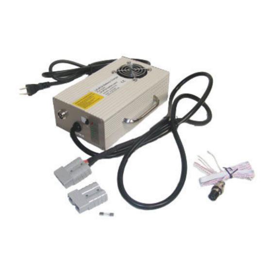
- Page 4 CAN and Digital Input Controls A five wire connector connects to the charger for interfacing with the BMS. Three wires have a white connector attached, these three wires are the CAN interface. The other two wires are labeled “+ 12V” and “- 12V”, these wires are the digital input used to control the charger from the BMS CPU.
- Page 5 For a CAN communication connection connect the CANH, CANL and CAN GND to the matching connection on the CAN connection on the BMS CPU. The white connector may be cut off of the cable; however, note which wires are which before doing so. CANH CANL CAN GND...
-
Page 6: Troubleshooting
If both the CAN communication and the digital inputs are connected CAN communications will take priority over the digital input for charge control. CAN communications requires the optional CAN board be installed on the BMS CPU. *Caution* The BMS CPU has a programming port on it marked “Rx, Tx, RES, VSS”.
Need help?
Do you have a question about the CH-PFC1215 and is the answer not in the manual?
Questions and answers