Table of Contents
Advertisement
Service
Manual
SECTION
1. TECHNICAL SPECIFICATIONS ................................................................................................................. 1
2. IC DATA ...................................................................................................................................................... 1
3. BLOCK DIAGRAM ....................................................................................................................................... 2
4. TEST EQUIPMENT REQUIRED FOR SERVICING .................................................................................... 2
5. SCHEMATIC DIAGRAM AND PARTS LOCATION (Pattern Side) ............................................................. 3
6. EXPLODED VIEW AND PARTS LIST ......................................................................................................... 7
7. POWER AMP. ALIGNMENT ..................................................................................................................... 10
8. ELECTRICAL PARTS LIST ....................................................................................................................... 11
Please use this service manual with referring to the user guide ( D.F.U. ) without fail.
Printed in Japan
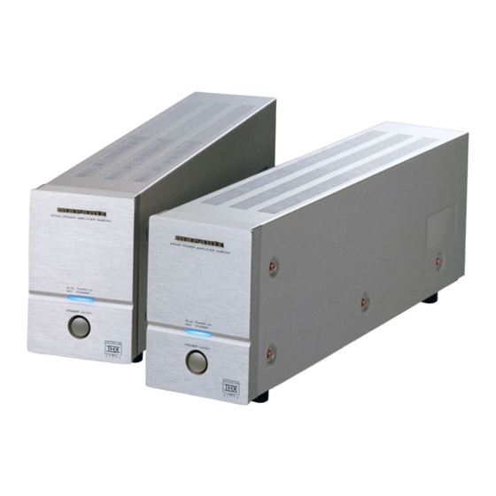
Mono Power Amplifier
MONO POWER AMPLIFIER MA6100
BLUE : POWER ON
RED : STANDBY
POWER
ON/OFF
TABLE OF CONTENTS
MA6100
MA6100 /
N1G, /U1G
/N1B, /U1B
PAGE
R
329J855010 MIT
3120 785 22380
First Issue 2000.07
Advertisement
Table of Contents

Related Manuals for Marantz MA6100


Summary of Contents for Marantz MA6100
-
Page 1: Table Of Contents
Service MA6100 / N1G, /U1G /N1B, /U1B Manual Mono Power Amplifier MONO POWER AMPLIFIER MA6100 BLUE : POWER ON RED : STANDBY POWER ON/OFF TABLE OF CONTENTS SECTION PAGE 1. TECHNICAL SPECIFICATIONS ......................... 1 2. IC DATA ..............................1 3. BLOCK DIAGRAM ............................2 4. -
Page 2: Ordering Parts
MARANTZ Parts for your equipment are generally available to our National Marantz Subsidiary or Agent. ORDERING PARTS : Parts can be ordered either by mail or by Fax.. In both cases, the correct part number has to be specified. -
Page 3: Technical Specifications
1. TECHNICAL SPECIFICATIONS 3. BLOCK DIAGRAM Rated power output (20 Hz to 20 kHz, 8 Ω load) ........125 W MAIN AMP Total harmonic distortion (20 Hz to 20 kHz, 8 Ω load) ........0.02 % INPUT +29.0dB SPK OUT Output bandwidth (8 Ω... -
Page 4: Schematic Diagram And Parts Location (Pattern Side)
5. SCHEMATIC DIAGRAM AND PARTS LOCATION (Pattern Side) J705 R745 R744 R725 DUMMY DUMMY C706 P701 MAIN 220/100V 1/4W 63.8 64.0 R707 D701 R714 R716 R718 D702 63.0 Q711 63.0 2SC4793 Q706 R727 C713 R736 R738 D707 Q703 2SA1360 120p HSS81 2SA1145 62.6... - Page 5 P701 PY01 Q802 Q803 Q701 Q702 QS01 QS02 QY03 QY04 Q705 Q707 Q704 Q704 Q703 Q715 QN02 QN01QS04 QS03 QY72 QY71 QY73 Q710 Q712 Q708 Q709 Q711 QY01 QY02 Q714 Q713 WA329J102-0/PY01 IDLING ADJ / DC OFFSET ADJ WA329J101-0/P701 D808 UY01 R801 U734...
-
Page 6: Exploded View And Parts List
6. EXPLODED VIEW AND PARTS LIST W 0 0 1 0 0 1 D U, K ONL Y 5 1 2 8 3 X 8 ( M) N ONL Y PART S NAME MA RK M A T E RI A L / F I NISH SYMBOL ST YL E 0 0 2 D( U ONL Y ) - Page 7 001B BLACK 9965 000 05897 FRONT AL PANEL BLACK 329J248010 001B GOLD 9965 000 05902 FRONT AL PANEL GOLD 329J248110 002B 9965 000 05898 BADGE MARANTZ 354H251240 003B 9965 000 05899 LENS 329J355010 FOR POWER ON/STANDBY 004B BLACK 9965 000 05900 CHASSIS FRONT MOLD BL...
-
Page 8: Power Amp. Alignment
7. POWER AMP. ALIGNMENT 7.1 DC offset Adjustment Speaker out:non Load Step Power Adjust. Point Test Point Adjustment Vaule R708 Speaker Output Terminal 20mV Note:If the value that measured is not exceed +-20mV,no need adjust the DC offset. 7.2 Iding current Adjustment Speaker out:non Load Step Power... -
Page 9: Electrical Parts List
8. ELECTRICAL PARTS LIST NOTE ON SAFETY FOR FUSIBLE RESISTOR : ASSIGNMENT OF COMMON PARTS CODES. RESISTORS The suppliers and their type numbers of fusible resistors : 1) GD05 × × × 140, Carbon film fixed resistor, ±5% 1/4W are as follows; : 2) GD05 ×... - Page 10 POS. VERS. PART NO. POS. VERS. PART NO. PART NO. PART NO. DESCRIPTION DESCRIPTION COLOR (FOR PCS) COLOR (FOR PCS) (MJI) (MJI) P701-MAIN/POWER SUPPLY R726 4822 052 10109 10Ω ±5% 1/4W GG05100140 CIRCUIT BOARD R727 4822 052 10101 100Ω ±5% 1/6W GG05101160 P701-CAPACITORS R728...
- Page 11 POS. VERS. PART NO. POS. VERS. PART NO. PART NO. PART NO. DESCRIPTION DESCRIPTION COLOR (FOR PCS) COLOR (FOR PCS) (MJI) (MJI) Q705 4822 130 43283 TRS. 2SC2705 O OR Y HT327052A0 CY05 4822 122 30043 CER. 0.01µF Z 50V DK18103310 Q706 5322 130 61728 TRS.
Need help?
Do you have a question about the MA6100 and is the answer not in the manual?
Questions and answers