Table of Contents
Advertisement
Quick Links
Advertisement
Table of Contents

Related Manuals for Panasonic SU-MED640E


Summary of Contents for Panasonic SU-MED640E
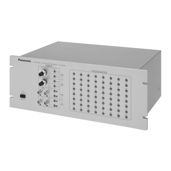
- Page 1 Panasonic 64-CHANNEL INTEGRATED AMPLIFIER Operating Instructions P/N: SU-MED640E...
-
Page 2: How To Replace The Fuse
Caution for AC main lead FOR YOUR SAFETY, PLEASE READ THE FOLLOWING TEXT CAREFULLY This product is equipped with 2 types of AC main cable. One is for continental Europe, etc. and the other one is only for UK. Appropriate main cable must be used in each local area, since the other type of main cable is not suitable. -
Page 3: Safety Precautions
Safety Precautions Before using this unit please read these operating instructions carefully. Take special care to follow the warnings indicated on the unit itself as well as the safety suggestions listed below. Keep these precau- tions handy for future reference. The unit may be used only in the operating conditions and positions specified manufacturer. -
Page 4: Environmental Conditions
Service - Never attempt to repair, disassemble or modify the unit if there seems to be a problem. A serious electric shock could result if you ignore this precautionary measure. - If a problem occurs during operation (smoke is detected, etc.) contact your dealer immediately. - Disconnect the power supply if the unit will not be used for a long time. -
Page 5: Components And Their Functions
Components and their functions Front panel (1) POWER To turn the amplifier on and off. Caution: Do NOT turn on the power with a "mini-plug" connected on the output terminal of the internal stimulators (#2, 3, 4 & 5). This may cause damage to the microelectrode(s) on the probe. (2) OUTPUT INT(V) [CH1] The output terminal for the variable, internal channel 1 (CH1) constant current stimulator. -
Page 6: Reference Electrodes
Back Panel (13) INPUT To connect to the MED probe, through the MED-CO3 connector, to the amplifier. (14) OUTPUT(1-32CH) To connect the output of channels 1-32 to the to the first A/D board in the computer. (15) OUTPUT(33-64CH) To connect the output of channels 33-64 to the to the second A/D board in the computer. (16) SIGNAL OUTPUT BNC connectors used to send analog outputs from selected recording channels to an external amplifier, signal processor, or other device (e.g. - Page 7 Connection to other components Usage of internal stimulus amplifier (Components and cables indicated with dashed lines are not included) MED Connector Connector cable (included) A/D board cables (NI SH-100100) A/D board in PC A/D board in PC (NI PCI-6071E) (NI PCI-6071E)
- Page 8 Using the MED64 amplifier with External Devices (stimulator, isolator, oscilloscope). Caution: Do NOT connect MED64 mini-plugs on the internal stimulator outputs (CH1 or CH2). (Components and cables indicated with dashed lines are not included.) External Stimulator External Isolator BNC cables External Stimulator External Isolator MED Connector...
-
Page 9: Precautions During Use
Precautions during use Always, turn ON the amplifier power BEFORE starting up the software. The software sends information to the Amplifier that is necessary for initialization of stimuli and the recorded data. Failure to do so (i.e. turn- ing ON power to the amplifier after the software starts up) will lead to inaccuracies in stimulus delivery and the data recorded. -
Page 10: Specifications
Specifications [Recording unit] Channels Input impedance > 10 MΩ Maximum output voltage +/- 12 Vp 150 Ω Output impedance Amplification 1000 times (1 mV/V, 60 dB) Low-cut filter 4 mode: 0.1, 1, 10 and 100 Hz (PC control, Stimulation 64 CH switch) Frequency range (low-cut: 0.1 Hz) 0.1 Hz to 10 kHz, +0 dB to -3 dB Internal noise... - Page 11 Matsushita Electric Industrial Co., LTD. 1-4 Matsuo-cho, Kadoma, Osaka 571-8505 Japan RQT5390-B...
Need help?
Do you have a question about the SU-MED640E and is the answer not in the manual?
Questions and answers