Advertisement
Table of Contents
- 1 Specifications
- 2 Hardware Setup
- 3 Layout Contents
- 4 Hardware Setup Procedure
- 5 Motherboard Settings
- 6 System Memory (DIMM)
- 7 General DIMM Notes
- 8 DIMM Memory Installation
- 9 Central Processing Unit (CPU)
- 10 Expansion Card Installation Procedure
- 11 Expansion Cards
- 12 Assigning Irqs for Expansion Cards
- 13 Standard Interrupt Assignments
- 14 Interrupt Request Table for this Motherboard
- 15 Accelerated Graphics Port
- 16 External Connectors
- Download this manual
1.1 The ASUS A7V-VM Motherboard
The A7V-VM motherboard is carefully designed for the demanding PC user who
wants high-performance features in a small package.
1.1.1 Specifications
•
AMD Athlon™ Processor Support: Supports AMD Athlon™ processor de-
signed for the AMD Athlon™ Processor Module (462-pin Socket A).
•
North Bridge System Chipset: VIA VT8363™ system controller supports a
200MHz Front Side Bus (FSB), supports up to 1GB of PC133/PC100 SDRAM/
Virtual Channel Memory (VCM) SDRAM, complies with AGP 2.0 specifica-
tions for 4X, 2X, and 1X AGP modes and PCI 2.2. bus interface with support for
5 PCI masters. It is optimized to deliver enhanced AMD Athlon™ processor
system performance.
•
South Bridge System Chipset: VIA VT82C686A PCIset with PCI Super I/O
integrated peripheral controller supports UltraDMA/66, which allows burst mode
data transfer rates of up to 66.6MB/sec.
•
PC133/PC100 Memory Support: Equipped with two DIMM sockets to sup-
port PC133/PC100-compliant SDRAMs (16, 32, 64, 128, 256, 512MB) up to
1GB.
•
Super Multi-I/O: Provides two high-speed UART compatible serial ports and
one parallel port with EPP and ECP capabilities.
•
Expansion Slots: Provides three 32-bit PCI 2.2 slots and one AGP expansion
slot. PCI supports up to 133MB/sec maximum throughput. Each PCI slot can sup-
port a Bus Master PCI card, such as a SCSI card.
•
Wake-Up Support: Supports Wake-On-LAN activity with onboard network
support.
•
AGP Slot: Supports an Accelerated Graphics Port card for high performance
component level interconnect targeted at 3D graphical display applications us-
ing 4X, 2X, or 1X mode bus.
•
USB: Supports up to 4 USB ports, two on the back panel and two midboard for
more peripheral connectivity options.
•
UltraDMA/66 & UltraDMA/33: Comes with an onboard PCI Bus Master IDE
controller with two connectors that support four IDE devices on two channels.
Supports UltraDMA/66, UltraDMA/33, PIO Modes 3 & 4 and Bus Master IDE
DMA Mode 2, and Enhanced IDE devices, such as DVD-ROM, CD-ROM, CD-
R/RW, LS-120, and Tape Backup drives.
•
Onboard LAN Controller: Features the Realtek 10/100Mb Fast Ethernet Con-
troller, which supports Wired for Management, remote wake-up, and OnNow
initiative to reduce Total Cost of Ownership (TCO).
•
Onboard Audio: Hardware AC'97 V2.1 CODEC compliant, Crystal's 3D sound
circuitry, sample rate conversion from 7kHz to 48kHz.
1. FEATURES
ASUS A7V-VM User's Manual
E604
1
Advertisement
Table of Contents

Related Manuals for Asus A7V-VM


Summary of Contents for Asus A7V-VM
-
Page 1: Specifications
E604 1. FEATURES 1.1 The ASUS A7V-VM Motherboard The A7V-VM motherboard is carefully designed for the demanding PC user who wants high-performance features in a small package. 1.1.1 Specifications • AMD Athlon™ Processor Support: Supports AMD Athlon™ processor de- signed for the AMD Athlon™ Processor Module (462-pin Socket A). - Page 2 PC 99 compliancy. The new PC 99 requirements for systems and components are based on the following high-level goals: Support for Plug and Play compatibility and power management for configuring and managing all system components, and 32-bit device drivers and installation procedures for Windows 95/98/NT. ASUS A7V-VM User’s Manual...
- Page 3 Remote Ring On (requires modem): This allows a computer with this motherboard to be turned on remotely through an internal or external modem. With this feature, users can access their computer from anywhere in the world! ASUS A7V-VM User’s Manual...
-
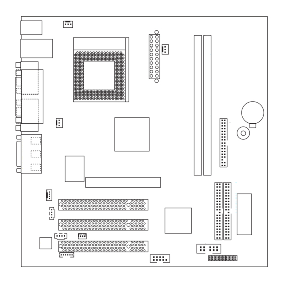
Page 4: Hardware Setup
2. HARDWARE SETUP 2.1 A7V-VM Motherboard Layout PS/2 T: Mouse CPU_FAN B: Keyboard Socket A Top: RJ-45 T: USB1 B: USB2 PS_FAN COM1 ATXPWR CR2032 3V Lithium Cell DOCT_FAN CMOS Power Buzzer VT8363 Chipset Line CLRTC Line Realtek Fast Enternet... -
Page 5: Layout Contents
Reset Switch Lead (2 pins) 20) PLED (PANEL) p.20 System Power LED Lead (3 pins) 21) IDELED (PANEL) p.21 IDE Activity LED Lead (2 pins) 22) PWR (PANEL) p.21 ATX Power / Soft-Off Switch Lead (2 pins) ASUS A7V-VM User’s Manual... -
Page 6: Hardware Setup Procedure
4. Place components on a grounded antistatic pad or on the bag that came with the compo- nent whenever the components are separated from the system. 5. Ensure that the ATX power supply is switched off before you plug in or remove the ATX power connector on the motherboard. ASUS A7V-VM User’s Manual... -
Page 7: System Memory (Dimm)
This motherboard does NOT support registered memory. • SDRAM chips are generally thinner with higher pin density than EDO (Ex- tended Data Output) chips. • Single-sided DIMMs come in 16, 32, 64,128, 256MB; double-sided come in 32, 64, 128, 256, 512MB. ASUS A7V-VM User’s Manual... -
Page 8: Dimm Memory Installation
20 Pins 60 Pins A7V-VM 88 Pins A7V-VM 168-Pin DIMM Sockets Lock The DIMMs must be 3.3V Unbuffered for this motherboard. To determine the DIMM type, check the notches on the DIMMs (see figure below). 168-Pin DIMM Notch Key Definitions (3.3V) -
Page 9: Central Processing Unit (Cpu)
CPU fan cable to it. CAUTION! Be careful not to scrape the motherboard when mounting a clamp- style processor fan or else damage may occur to the motherboard. BLANK LEVER LOCK NOTCH AMD™ Athlon A7V-VM A7V-VM Socket A ASUS A7V-VM User’s Manual... -
Page 10: Expansion Card Installation Procedure
6 IRQs free for expansion cards. If your motherboard has PCI audio onboard, an additional IRQ will be used. If your moth- erboard also has MIDI enabled, another IRQ will be used, leaving 4 IRQs free. ASUS A7V-VM User’s Manual... -
Page 11: Standard Interrupt Assignments
If using PCI cards on shared slots, make sure that the drivers support “Share IRQ” or that the cards do not need IRQ assignments. Conflicts will arise between the two PCI groups that will make the system unstable or cards inoperable. ASUS A7V-VM User’s Manual... -
Page 12: Accelerated Graphics Port
ASUS 3D graphics accelerator. CAUTION! To avoid damaging your graphics card, it is highly recommended that you turn off your computer’s power supply before inserting your graphics card into the slot. A7V-VM A7V-VM Accelerated Graphics Port (AGP) ASUS A7V-VM User’s Manual... -
Page 13: External Connectors
This connection is for a standard keyboard using an PS/2 plug (mini DIN). This connector will not allow standard AT size (large DIN) keyboard plugs. You may use a DIN to mini DIN adapter on standard AT keyboards. PS/2 Keyboard (6-pin female) ASUS A7V-VM User’s Manual... - Page 14 5) Parallel Port Connector (25-pin PRINTER) You can enable the parallel port and choose the IRQ through Onboard Parallel Port in the BIOS. NOTE: Serial printers must be connected to the serial port. Parallel (Printer) Port (25-pin female) ASUS A7V-VM User’s Manual...
- Page 15 Serial Port (9-pin male) COM2 PIN 1 A7V-VM A7V-VM Serial COM2 Bracket 7) Game/MIDI Connector (15-pin GAME_AUDIO) You may connect game joysticks or game pads to this connector for playing games. Connect MIDI devices for playing or editing professional audio.
- Page 16 IMPORTANT: UltraDMA/66 IDE devices must use a 40-pin 80-conductor IDE cable for 66MBytes/s transfer rates. NOTE: Orient the red markings (usually zigzag) on the IDE ribbon cable to PIN 1. A7V-VM PIN 1 A7V-VM IDE Connectors ASUS A7V-VM User’s Manual...
- Page 17 CPU and onboard heatsinks. Damage may occur to the motherboard and/or the CPU fan if these pins are incorrectly used. These are not jumpers, do not place jumper caps over these pins. CPU_FAN PS_FAN FAN_SUS# DOCT_FAN +12V A7V-VM Rotation A7V-VM 12-Volt Cooling Fan Power ASUS A7V-VM User’s Manual...
- Page 18 PIN 1 A7V-VM PIN 1 A7V-VM Floppy Disk Drive Connector 12) USB Header (12-2 pin HP_USB) If the USB Ports on the back panels are inadequate, connect an optional USB connector set to this header and mount it to an open slot on your chassis.
- Page 19 Left Audio Channel Ground Right Audio Channel A7V-VM Audio Codec Setting 14) Wake-On-LAN Connector (3-pin WOL_CON) This connector connects to a LAN card with a Wake-On-LAN output. The con- nector powers up the system when a wakeup packet or signal is received through the LAN card.
- Page 20 -12.0 Volts +3.3 Volts +3.3 Volts A7V-VM ATX Power Connector 16) System Message LED Lead (2-pin MLED) This indicates whether a message has been received from a fax/modem. The LED will remain lit when there is no signal and blink when there is data re- ceived.
- Page 21 The system power LED shows the status of the system’s power. SMI Lead Speaker Message LED Connector A7V-VM ATX Power Reset SW Switch* IDELED Power LED Requires an ATX power supply. A7V-VM System Panel Connectors ASUS A7V-VM User’s Manual...
- Page 22 2. HARDWARE SETUP (This page was intentionally left blank.) ASUS A7V-VM User’s Manual...
Need help?
Do you have a question about the A7V-VM and is the answer not in the manual?
Questions and answers