Sign In
Upload
Download
Table of Contents
Contents
Add to my manuals
Delete from my manuals
Share
URL of this page:
HTML Link:
Bookmark this page
Add
Manual will be automatically added to "My Manuals"
Print this page
×
Bookmark added
×
Added to my manuals
Manuals
Brands
Hitachi Manuals
Projector
CP-S420
User manual
Hitachi CP-S420 User Manual
Liquid crystal projector
Hide thumbs
Also See for CP-S420
:
User manual
(39 pages)
1
Table Of Contents
2
3
4
5
6
7
8
9
10
11
12
13
14
15
16
17
18
19
20
21
22
23
24
25
26
27
28
29
30
31
32
33
34
35
36
37
38
39
page
of
39
Go
/
39
Contents
Table of Contents
Troubleshooting
Bookmarks
Table of Contents
Table of Contents
Features
Before Use
Contents of Package
Part Names
Loading the Batteries
Tables
Installation
Installation of the Projector and Screen
Angle Adjustment
Table 1. Installation Reference
Cabling
Table 2. Cabling
Power Connection
Example of System Setup
Plug & Play
Operations
Power on
Power off
Basic Operation
Table 3. Basic Operation
Setup Menu
Table 4. Setup Menu
Input Menu
Table 5. Input Menu
Image Menu
Table 6. Image Menu
Options Menu
Table 7. Options Menu
No Signal Menu
Table 8. no Signal Menu
Maintenance
Lamp
Replacing the Lamp
Resetting the Lamp Timer
Air Filter
Other Maintenance
Troubleshooting
OSD Message
Table 9. OSD Message
Indicators Message
Table 10. Indicators Message
Symptom
Table 11. Symptom
Specifications
Table 12. Specifications
Warranty and After-Service
Dimension Diagram
Example of Computer Signal
Serial Mouse
Usb Mouse
Communications Setting
Command Data Chart
Regulatory Notices
Advertisement
Quick Links
Download this manual
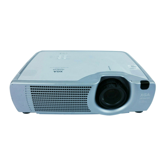
Liquid Crystal Projector
CP-S420/CP-X430
CP-S420WA/CP-X430WA/CP-X430W
USER'S MANUAL
Please read this user's manual thoroughly to ensure correct usage through understanding.
Downloaded from
www.Manualslib.com
manuals search engine
Table of
Contents
Previous
Page
Next
Page
1
2
3
4
5
Advertisement
Table of Contents
Need help?
Do you have a question about the CP-S420 and is the answer not in the manual?
Ask a question
Questions and answers
Related Manuals for Hitachi CP-S420
Projector Hitachi CP-X430 User Manual
Liquid crystal projector (39 pages)
Projector Hitachi CP-S420WA Service Manual
Multimedia (60 pages)
Projector Hitachi CP-X430W Service Manual
Multimedia (58 pages)
Projector Hitachi CPX430W User Manual
Hitachi user's manual liquid crystal projector cpx430w (40 pages)
Projector Hitachi CPX430WA User Manual
Liquid crystal projector (40 pages)
Projector Hitachi CP-X430W Specifications
Brochure (2 pages)
Projector Hitachi CP-S235 User Manual
Digital projectors (46 pages)
Projector Hitachi CP-SX1350 Operating Manual
(65 pages)
Projector Hitachi CP-S335 User's Manual And Operating Manual
Hitachi cp-s335: owners manual (74 pages)
Projector Hitachi CP-S335 Quick Start Manual
Quick start guide (10 pages)
Projector Hitachi CP-S335 Service Manual
Multimedia lcd projector. (72 pages)
Projector Hitachi CP-S210 User Manual
(55 pages)
Projector Hitachi CP-S220W User Manual
Liquid crystal projector (26 pages)
Projector Hitachi CP-S245 User Manual
(108 pages)
Projector Hitachi CP-X8150 User Manual
(304 pages)
Projector Hitachi CP-X8150 User Manual
(128 pages)
This manual is also suitable for:
Cp-x430
Cp-s420wa
Cp-x430wa
Cp-x430w
Table of Contents
Print
Rename the bookmark
Delete bookmark?
Delete from my manuals?
Login
Sign In
OR
Sign in with Facebook
Sign in with Google
Upload manual
Upload from disk
Upload from URL


Need help?
Do you have a question about the CP-S420 and is the answer not in the manual?
Questions and answers