Table of Contents
Advertisement
SPLIT-TYPE, HEAT PUMP AIR CONDITIONERS
INDOOR UNIT
SERVICE MANUAL
Wireless type
Models
MSZ-GA22VA -
MSZ-GA22VA -
MSZ-GA22VA -
MSZ-GA25VA -
MSZ-GA25VA -
MSZ-GA25VA -
MSZ-GA35VA -
MSZ-GA35VA -
MSZ-GA35VA -
NOTE:
RoHS compliant products have <G> mark on the spec name plate.
For servicing of RoHS compliant products, refer to the RoHS Parts List.
Please void OB378 REVISED EDITION-B.
E1
E2
E3
E1
E2
E3
E1
E2
E3
CONTENTS
1. TECHNICAL CHANGES ····································2
2. PART NAMES AND FUNCTIONS······················3
3. SPECIFICATION·················································5
4. NOISE CRITERIA CURVES ·······························6
5. OUTLINES AND DIMENSIONS ·························7
6. WIRING DIAGRAM ············································8
7. REFRIGERANT SYSTEM DIAGRAM ················8
8. SERVICE FUNCTIONS ······································9
9. TROUBLESHOOTING······································10
10. DISASSEMBLY INSTRUCTIONS·····················24
11. PARTS LIST······················································27
12. RoHS PARTS LIST···········································31
13. OPTIONAL PARTS···········································34
No. OB378
REVISED EDITION-C
Outdoor unit service manual
MUZ-GA·VA Series (OB379)
MXZ-A·VA Series (OB377)
MXZ-8A140VA
(OC316)
1
Advertisement
Table of Contents
Troubleshooting

Related Manuals for Mitsubishi Electric MSZ-GA22VA - E1


Summary of Contents for Mitsubishi Electric MSZ-GA22VA - E1
-
Page 1: Table Of Contents
Revision C: • 3.SPECIFICATION has been corrected. SPLIT-TYPE, HEAT PUMP AIR CONDITIONERS Please void OB378 REVISED EDITION-B. INDOOR UNIT No. OB378 SERVICE MANUAL REVISED EDITION-C Wireless type Models MSZ-GA22VA - MSZ-GA22VA - MSZ-GA22VA - MSZ-GA25VA - MSZ-GA25VA - MSZ-GA25VA - MSZ-GA35VA - Outdoor unit service manual MSZ-GA35VA -... -
Page 2: Specification Has Been Corrected
Revision A: • MSZ-GA·VA- has been added. Color of BOX and CORNER BOX has been changed to white. Revision B: • model has been added. • Failure mode recall function(9-2.) has been changed. • RoHS PARTS LIST has been added. Revision C: •... -
Page 3: Part Names And Functions
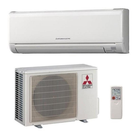
PART NAMES AND FUNCTIONS MSZ-GA22VA MSZ-GA25VA MSZ-GA35VA Air inlet Heat exchanger Front panel Panel Air cleaning filter (Optional parts,Anti- Allergy Enzyme Filter, Blue bellows type) Fan guard Catechin air filter Air outlet Vertical vane Horizontal vane Remote controller Line flow fan Display section Operation section (When the front panel is opened) -
Page 4: Remote Controller
MSZ-GA22VA MSZ-GA25VA MSZ-GA35VA ACCESSORIES Installation plate Installation plate fixing screw 4 o 25 mm Remote controller holder Fixing screw for 3 3.5 o 1.6 mm (Black) Battery (AAA) for remote controller Wireless remote controller Felt tape (Used for left or left-rear piping) REMOTE CONTROLLER Signal transmitting section Operation display section... - Page 5 SPECIFICATION Indoor model MSZ-GA22VA MSZ-GA25VA MSZ-GA35VA Heating Cooling Heating Cooling Cooling Heating Function Single phase Single phase Single phase Power supply 230V,50Hz 230V,50Hz 230V,50Hz Air flow(Super High/High) 600/480 630/504 600/480 486/408 600/480 630/504 630/504 Capacity K /h Air flow(Med./Low) 336/258 366/246 366/234 384/258...
-
Page 6: Hearing For
NOISE CRITERIA CURVES MSZ-GA22VA MSZ-GA35VA MSZ-GA25VA SPL(dB(A)) FAN SPEED FUNCTION LINE FAN SPEED FUNCTION SPL(dB(A)) LINE COOLING COOLING Super High Super High HEATING HEATING Test conditions Test conditions Cooling : Dry-bulb temperature 27: Wet-bulb temperature 19: Cooling : Dry-bulb temperature 27: Wet-bulb temperature 19: Heating : Dry-bulb temperature 20: Wet-bulb temperature 15: Heating : Dry-bulb temperature 20: Wet-bulb temperature 15: NC-70... -
Page 7: Outlines And Dimensions
OUTLINES AND DIMENSIONS Unit : mm MSZ-GA22VA MSZ-GA25VA MSZ-GA35VA 11X26 Oblong hole 11X20 Oblong hole Installation plate Air in Wall hole [65 Indoor unit Installation plate Liquid line [6.35-0.5m Gas line [9.52-0.43m Insulation [35 O.D [19 I.D Drain hose [16 (Connected part O.D) 53.5 624.5... -
Page 8: Wiring Diagram
WIRING DIAGRAM MSZ-GA22VA MSZ-GA25VA MSZ-GA35VA INDOOR ELECTRONIC CONTROL P.C. BOARD RT13 TAB3 230V~ RT12 DB111 T111 TO OUTDOOR UNIT RT11 12-24V NR11 CONNECTING CN201 LD104 CN211 101(A) 105(T) INTERLOCK POWER MONITOR SW P.C. SWITCH(FAN) RECEIVER P.C.BOARD BOARD SYMBOL NAME SYMBOL NAME DB111 DIODE STACK... -
Page 9: Service Functions
SERVICE FUNCTIONS MSZ-GA22VA MSZ-GA25VA MSZ-GA35VA 8-1. TIMER SHORT MODE For service, set time can be shortened by short circuit of JPG and JPS the electronic control P.C. board. The time will be shortened as follows. (Refer to 9-7.) Set time : 1-minute 1-second Set time : 3-minute 3-second (It takes 3 minutes for the compressor to start operation. -
Page 10: Troubleshooting
8-3. AUTO RESTART FUNCTION When the indoor unit is controlled with the remote controller, the operation mode, the set temperature, and the fan speed are memorized by the indoor electronic control P.C. board. The “AUTO RESTART FUNCTION” sets to work the moment power has restored after power failure. -
Page 11: Heating
3. Troubleshooting procedure 1) First, check if the OPERATION INDICATOR lamp on the indoor unit is flashing on and off to indicate an abnormality. To make sure, check how many times the abnormality indication is flashing on and off before starting service work. 2) Before servicing, check that the connector and terminal are connected properly. -
Page 12: Failure Mode Recall Function
9-2. Failure mode recall function Outline of the function This air conditioner can memorize the abnormal condition which has occurred once. Even though LED indication listed on the troubleshooting check table (9-4.) disappears, the memorized failure details can be recalled. This mode is very useful when the unit needs to be repaired for the abnormality which doesn't recur. - Page 13 2. Indoor unit failure mode table Left lamp of OPERATION Abnormal point Condition Correspondence INDICATOR lamp (Failure mode) Not lighted Normal – – The room temperature thermistor short or Room temperature Refer to the characteristics of the room 1-time flash open circuit is detected every 8 seconds thermistor temperature thermistor (Refer to 9-7.).
- Page 14 9-3. Instruction of troubleshooting Start Indoor unit Indoor unit Indoor unit operates. OPERATION INDICATOR operates. doesn't receive Outdoor unit doesn't lamp on the indoor unit is Outdoor unit the signal from operate normally. flashing on and off. doesn't remote controller. operate.
-
Page 15: Troubleshooting Check Table
9-4. Troubleshooting check table Before taking measures, make sure that the symptom reappears for accurate troubleshooting. When the indoor unit has started operation and the following detection method has detected an abnormality (the first detection after the power ON), the indoor electronic control P.C. board turns OFF the indoor fan motor with OPERATION INDICATOR lamp flashing. -
Page 16: Trouble Criterion Of Main Parts
Lighted · Flashing of OPERATION INDICATOR lamp (all lamps) indicates abnormality. OPERATION INDICATOR Blinking Not lighted Abnormal Operation indicator lamp Symptom Condition Correspondence point All lamps flash at the same time. Attachment Indoor unit • Refer to 9-6.E "Check of The electricity is not conducted to the interlock 0.5-second ON of the... -
Page 17: Troubleshooting Flow
9-6. Troubleshooting flow When OPERATION INDICATOR lamp flashes 3-time. Indoor fan does not operate. Check of indoor fan motor The indoor fan motor error has occurred, and the indoor fan doesn't operate. Turn OFF the power supply. Pay careful attention to the high voltage on the fan motor connector CN211. -
Page 18: Check Of Remote Controller And Receiver P.c. Board
Indoor unit operates by pressing EMERGENCY OPERATION switch, but does not operate with the remote controller. Check of remote controller and receiver P.C. board wCheck if the remote controller is exclusive for this air conditioner. Press OPERATE/STOP(ON/OFF) button on the remote controller. Is LCD display on the the remote Replace the batteries. - Page 19 The unit does not operate with the remote controller. Also, OPERATION INDICATOR lamp does not light up by pressing EMERGENCY OPERATION switch. Check of indoor electronic control P.C. board and indoor fan motor Turn OFF the power supply. Measure the resistance between CN211 3 Remove indoor fan motor connector CN211 and Short/open circuit: and 4 of the indoor fan motor connector.
- Page 20 • When unit cannot operate neither by the remote controller nor by EMERGENCY OPERATION switch. Indoor unit does not operate. • When OPERATION INDICATOR lamp flashes ON and OFF every 0.5-second. Outdoor unit does not operate. How to check mis-wiring and serial signal error Turn OFF the power supply.
- Page 21 When all lamps flash ON and OFF every 0.5-second. Indoor unit and outdoor unit do not operate. Check of installation of the horizontal vane Turn OFF the power supply. Relock the stopper of the Is the stopper of the horizontal vane horizontal vane to the indoor unit.
-
Page 22: Electromagnetic Noise Enters Into Tv Sets Or Radios
Electromagnetic noise enters into TV sets or radios Is the unit earthed? Earth the unit. Is the distance between the Extend the distance between antennas and the indoor the antennas and the indoor unit within 3m, or is the unit, and/or the antennas and distance between the the outdoor unit. - Page 23 9-7. Test point diagram and voltage MSZ-GA22VA MSZ-GA25VA MSZ-GA35VA Indoor electronic control P.C. board Power supply input Varistor (NR11) 230V AC Fuse(F11) (T3.15AL250V) R111 Indoor fan motor (CN211) 1311V DC 3(-) Fiducial terminal of cathode side on measur- ing high-voltage DC 415V DC 5(+)3-6V DC Release of Auto restart...
-
Page 24: Disassembly Instructions
DISASSEMBLY INSTRUCTIONS <"Terminal with locking mechanism" Detaching points> The terminal which has the locking mechanism can be detached as shown below. There are two types ( Refer to (1) and (2)) of the terminal with locking mechanism. The terminal without locking mechanism can be detached by pulling it out. Check the shape of the terminal before detaching. - Page 25 OPERATING PROCEDURE PHOTOS Photo 2 2. Removing the electronic control P.C. board, the power monitor receiver P.C. board, SW P.C. board and the terminal block (1) Remove the horizontal vane, the panel (Refer to 1.) and the corner box. (2) Remove the screw of V.A. clamp, and then the indoor/outdoor connecting wire.
- Page 26 OPERATING PROCEDURE PHOTOS Photo 5 4. Removing the horizontal vane motor unit (1) Remove the horizontal vane and the panel. (Refer to 1.) (2) Remove the screws of the horizontal vane motor unit, and pull out the horizontal vane motor unit. (See Photo 5.) Screws of the (3) Disconnect the connector from the horizontal vane motor horizontal vane...
-
Page 27: Parts List
PARTS LIST (non-RoHS compliant) MSZ-GA22VA MSZ-GA25VA 11-2. ACCESSORY AND REMOTE MSZ-GA35VA CONTROLLER 11-1. INDOOR UNIT STRUCTURAL PARTS (See 13.) 11-1. INDOOR UNIT STRUCTURAL PARTS Q'ty/unit Symbol MSZ-GA22VA- MSZ-GA25VA- MSZ-GA35VA- Part No. Part name in Wiring Remarks Diagram E02 897 234 E02 A32 234 E02 915 000 PANEL ASSEMBLY... - Page 28 PARTS LIST (non-RoHS compliant) MSZ-GA22VA MSZ-GA25VA MSZ-GA35VA 11-3. INDOOR UNIT ELECTRICAL PARTS AND FUNCTIONAL PARTS 11-4. INDOOR UNIT HEAT EXCHANGER...
- Page 29 PARTS LIST (non-RoHS compliant) 11-3. INDOOR UNIT ELECTRICAL PARTS AND FUNCTIONAL PARTS Q'ty/unit Symbol MSZ-GA22VA- MSZ-GA25VA- MSZ-GA35VA- in Wiring Part No. Part name Remarks Diagram E02 751 509 BEARING MOUNT E02 001 504 SLEEVE BEARING E02 897 702 DRAIN HOSE E02 915 235 NOZZLE ASSEMBLY UP &...
-
Page 31: Rohs Parts List
RoHS PARTS LIST (RoHS compliant) MSZ-GA22VA MSZ-GA25VA 12-2. ACCESSORY AND REMOTE MSZ-GA35VA CONTROLLER 12-1. INDOOR UNIT STRUCTURAL PARTS (See 13.) 12-1. INDOOR UNIT STRUCTURAL PARTS Q'ty/unit Symbol MSZ-GA22VA- MSZ-GA25VA- MSZ-GA35VA- Part No. in Wiring Part name Remarks Diagram E12 A32 234 E12 915 000 PANEL ASSEMBLY Including No.3,4... - Page 32 RoHS PARTS LIST (RoHS compliant) MSZ-GA22VA MSZ-GA25VA MSZ-GA35VA 12-3. INDOOR UNIT ELECTRICAL PARTS AND FUNCTIONAL PARTS 12-4. INDOOR UNIT HEAT EXCHANGER...
- Page 33 RoHS PARTS LIST (RoHS compliant) 12-3. INDOOR UNIT ELECTRICAL PARTS AND FUNCTIONAL PARTS Q'ty/unit Symbol MSZ-GA22VA- MSZ-GA25VA- MSZ-GA35VA- in Wiring Part No. Part name Remarks Diagram BEARING MOUNT E12 751 509 E12 001 504 SLEEVE BEARING E12 897 702 DRAIN HOSE E12 915 235 NOZZLE ASSEMBLY UP &...
-
Page 34: Optional Parts
OPTIONAL PARTS 13-1. AIR CLEANING FILTER (ANTI-ALLERGY ENZYME FILTER) AIR CLEANING FILTER removes fine dust of 0.01 micron from air by means of static electricity. Normal life of AIR CLEANING FILTER is 1 year. If AIR CLEANING FILTER is to be washed, soak AIR CLEANING FILTER in water (when showing dirt, in lukewarm water) and rinse it delicately, without removing the filter from the frame about once every 3 months. - Page 36 HEAD OFFICE: TOKYO BLDG., 2-7-3, MARUNOUCHI, CHIYODA-KU, TOKYO 100-8310, JAPAN C C Copyright 2005 MITSUBISHI ELECTRIC ENGINEERING CO.,LTD Distributed in Apr. 2007. No. OB378 REVISED EDITION-C 6 Distributed in Jan. 2007. No. OB378 REVISED EDITION-B 6 Distributed in Jan. 2006. No. OB378 REVISED EDITION-A 6 New publication, effective Apr.
Need help?
Do you have a question about the MSZ-GA22VA - E1 and is the answer not in the manual?
Questions and answers