
Summary of Contents for Sure Electronics 3216
- Page 1 3216 Bicolor LED 3mm (5mm) Dot Matrix Display Information Board User’s Guide 2004-2009 Sure Electronics Inc. DE-DP14112&DE-DP14211 _Ver1.1...
-
Page 2: Table Of Contents
5.1 Schematic ......................14 5.2 Sample Code ..................... 15 5.3 Heat Dissipation ....................22 5.3.1 3216 Bicolor LED 3mm Dot Matrix Display Info Board......... 22 5.3.2 3216 Bicolor LED 5mm Dot Matrix Display Info Board......... 23 Chapter 6. Contact Us .....................25 DE-DP14112&DE-DP14211_Ver1.1_Page i... - Page 3 3216 Bicolor LED 3mm (5mm) Dot Matrix Display Information Board NOTES: Product Version Ver 1.0 Document Version Ver 1.1 2004-2009 Sure Electronics Inc DE-DP14112&DE-DP14211_Ver1.1_Page ii...
-
Page 4: Chapter 1. Overview
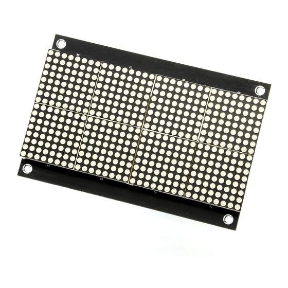
Chapter 1. Overview 1.1 Overview Thanks for using 3216 bicolor LED dot matrix info board series by Sure Electronics. Integrating four HT1632Cs as driver chips on each info board, these info boards support 16-level PWM brightness control and all LED dot matrixes displayed are mapped to the RAM of HT1632Cs. - Page 5 3216 Bicolor LED 3mm (5mm) Dot Matrix Display Information Board FIGURE 1-2 FRONT VIEW OF 3216 LED 5MM DOT MATRIX DISPLAY INFO BOARD FIGURE 1-3 BACK VIEW OF 3216 LED 3MM DOT MATRIX DISPLAY INFO BOARD FIGURE 1-4 BACK VIEW OF 3216 LED 5MM DOT MATRIX DISPLAY INFO BOARD 2004-2009 Sure Electronics Inc DE-DP14112&DE-DP14211_Ver1.1_Page 2...
-
Page 6: Quick Start
1.2.1 Connection of One Info Board and The Driver Board Connect BR1 of the info board and BR1 of the driver board with a 16-pin IDC cable. FIGURE 1-6 CONNECTION OF THE DRIVER BOARD AND ONE INFO BOARD 2004-2009 Sure Electronics Inc. DE-DP14112&DE-DP14211_Ver1.1_Page 3... -
Page 7: Connection Of Many Info Boards
Connect BR1 of the driver board and BR1 of the info board with a 16-pin IDC cable. Then, as shown in figure 1-7, connect two 3216 info boards and the driver board with two16-pin IDC cables and power cords. - Page 8 Overview FIGURE 1-8 CONNECTION OF TWO 3216 BICOLOR 5MM LED DOT MATRIX DISPLAY INFO BOARDS IN SERIES Program the chip on the driver board to control the LED display. Note: If you use the sample codes, all the boards will display the same content.
-
Page 9: Chapter 2. Hardware Detail
3216 BICOLOR LED 3MM (5MM) DOT MATRIX DISPLAY INFORMATION BOARD USER’S GUIDE Chapter 2. Hardware Detail 2.1 Hardware 8 pieces of 8*8 bicolor LED dot matrix Light-emitting diameter of DE-DP14112 is 3mm. Light-emitting diameter of DE-DP14211 is 5mm. LED drive chip (U2, U3, U5, and U6): four HT1632C chips, QFP packaging. -
Page 10: Display Memory
3216 Bicolor LED 3mm (5mm) Dot Matrix Display Information Board 2.3 Display Memory Display is controlled by modifying the data stored in RAM of HT1632Cs. Every two 8*8 dot matrix displays on the board are controlled by one HT1632C, as shown in the following figure 2-2. -
Page 11: Command Format
HT1632C. When the transmission is complete, CS must be reset to high. Enabling U2 (HT1632C) to individually send data to some address space is taken as an example. The timing diagram is shown as follows: 2004-2009 Sure Electronics Inc DE-DP14112&DE-DP14211_Ver1.1_Page 8... -
Page 12: Command Summary
3216 Bicolor LED 3mm (5mm) Dot Matrix Display Information Board FIGURE 2-3 TIMING DIAGRAM CS_BR1 CLK_BR1 QA_74164 QB_74164 QC_74164 QD_74164 DATA A6 A0 D0 D3 Command C8 C0 C8 C0 command_1 command_n Note: You may refer to HT1632C data sheet for details. - Page 13 Hardware Detail FIGURE 2-4 COMMAND SUMMARY 2004-2009 Sure Electronics Inc DE-DP14112&DE-DP14211_Ver1.1_Page 10...
-
Page 14: Chapter 3. Electrical Characteristics
3216 BICOLOR LED 3MM (5MM) DOT MATRIX DISPLAY INFORMATION BOARD USER’S GUIDE Chapter 3. Electrical Characteristics TABLE 3-1 ELECTRICAL CHARACTERISTICS Parameter Symbol Value Unit Operating Voltage Storage Temperature -20 to 80 Average Operating Current avrg Maximum Operating Current 1.37 (All LEDs on, 100% PWM duty cycle) DE-DP14112&DE-DP14211_Ver1.1_Page 11... -
Page 15: Chapter 4. Mechanical Drawing
3216 BICOLOR LED 3MM (5MM) DOT MATRIX DISPLAY INFORMATION BOARD USER’S GUIDE Chapter 4. Mechanical Drawing FIGURE 4-1 MECHANICAL DRAWING OF ONE 3216 BICOLOR LED 3MM DOT MATRIX DISPLAY INFO BOARD Symbol inch 5.05 4.65 3.20 2.80 2.54 0.06 128.27 118.11... - Page 16 3216 Bicolor LED 3mm (5mm) Dot Matrix Display Information Board FIGURE 4-2 MECHANICAL DRAWING OF ONE 3216 BICOLOR LED 5MM DOT MATRIX DISPLAY INFO BOARD Symbol inch 9.50 8.90 5.80 5.20 4.74 0.06 241.30 226.06 147.32 132.08 120.40 1.50 2004-2009 Sure Electronics Inc.
-
Page 17: Chapter 5. Appendix
3216 BICOLOR LED 3MM (5MM) DOT MATRIX DISPLAY INFORMATION BOARD USER’S GUIDE Chapter 5. Appendix 5.1 Schematic FIGURE 5-1 SCHEMATIC DE-DP14112&DE-DP14211_Ver1.1_Page 14 2004-2009 Sure Electronics Inc. -
Page 18: Sample Code
3216 Bicolor LED 3mm (5mm) Dot Matrix Display Information Board 5.2 Sample Code The driver board DE-DD210, integrating PIC16F723 as its master chip, is used as an example. This sample code is used to illuminate the odd rows of LEDs in green. - Page 19 //HT1632Cs void AddressWriteHT1632C(unsigned char address);//Write Address to HT1632Cs void SPI_ModelConfigure(void); void SPI_DataSend(const unsigned char data); void main() unsigned char i, j; SystemInit(); //System Initialization SetHT1632C_As3208(); //Set all HT1632Cs to work in 32*8 master mode 2004-2009 Sure Electronics Inc DE-DP14112&DE-DP14211_Ver1.1_Page 16...
- Page 20 3216 Bicolor LED 3mm (5mm) Dot Matrix Display Information Board for(i=1; i<=CHIP_MAX; i++) ChipSelect(i); //Chip select the corresponding HT1632C AddressWriteHT1632C(0x00); //Get the selected start address of the chip SPI_ModelConfigure(); //Open SPI mode, continuously send data to HT1632C for(j=0; j<32; j++) //Take “0x00”...
- Page 21 //Input Argument: x: if x=1, 74164 outputs high. If x 1, 74164 outputs low. //Output Argument: void //************************************************************************************************** void OutputA_74164(unsigned char x) //Input a digital level to 74164 if(x==1) A_74164 = 1; CLK_DELAY; else A_74164 = 0; CLK_DELAY; 2004-2009 Sure Electronics Inc DE-DP14112&DE-DP14211_Ver1.1_Page 18...
- Page 22 3216 Bicolor LED 3mm (5mm) Dot Matrix Display Information Board //************************************************************************************************** //Function Name: CommandWriteHT1632C //Function Feature: Write control commands to all HT1632Cs //Input Argument: command words written to “command”, specifically stated in “declare” //function //Output Argument: void //Argument Description: compile control commands to all external HT1632Cs for the...
- Page 23 //Function Feature: enable HT1632C //Input Argument: select: HT1632C to be selected If select=0, select none. If s<0, select all. //Output Argument: void //************************************************************************************************** void ChipSelect(int select) unsigned char tmp = 0; if(select<0) //Enable all HT1632Cs 2004-2009 Sure Electronics Inc DE-DP14112&DE-DP14211_Ver1.1_Page 20...
- Page 24 3216 Bicolor LED 3mm (5mm) Dot Matrix Display Information Board OutputA_74164(0); CLK_DELAY; for(tmp=0; tmp<CHIP_MAX; tmp++) OutputCLK_Pulse(); else if(select==0) //Disable all HT1632Cs OutputA_74164(1); CLK_DELAY; for(tmp=0; tmp<CHIP_MAX; tmp++) OutputCLK_Pulse(); else OutputA_74164(1); CLK_DELAY; for(tmp=0; tmp<CHIP_MAX; tmp++) OutputCLK_Pulse(); OutputA_74164(0); CLK_DELAY; OutputCLK_Pulse(); CLK_DELAY; OutputA_74164(1); CLK_DELAY;...
-
Page 25: Heat Dissipation
Following are pictures of heat dissipation gained by Fluke Ti20 Thermal Imager in the condition of info board working at full load, all LEDs on and 100% PWM duty cycle. 5.3.1 3216 Bicolor LED 3mm Dot Matrix Display Info Board FIGURE 5-2 HEAT DISTRIBUTION OF THE BACK PANEL 2004-2009 Sure Electronics Inc DE-DP14112&DE-DP14211_Ver1.1_Page 22... -
Page 26: 3216 Bicolor Led 5Mm Dot Matrix Display Info Board
3216 Bicolor LED 3mm (5mm) Dot Matrix Display Information Board FIGURE 5-3 HEAT DISTRIBUTION OF THE FRONT PANEL Note: The temperature around U2, U3, U5 and U6 is much higher when 3216 bicolor LED 5mm dot matrix display info board product works at full load. Take care and ensure good heat dissipation when using this product. - Page 27 Appendix FIGURE 5-5 HEAT DISTRIBUTION OF THE FRONT PANEL Note: It’s recommended to use these products in a good thermal environment. 2004-2009 Sure Electronics Inc DE-DP14112&DE-DP14211_Ver1.1_Page 24...
-
Page 28: Chapter 6. Contact Us
3216 BICOLOR LED 3MM (5MM) DOT MATRIX DISPLAY INFORMATION BOARD USER’S GUIDE Chapter 6. Contact Us Sure Electronics Co., Ltd. 5F, Zone A, Qinhuai Technology Innovation Center 105-2 DaMing Rd (ZIP:210022) Nanjing P.R.China Tel: +86-13601408832 (For technical questions only) +86-25-66606340 (English service, from GMT1-10AM)
Need help?
Do you have a question about the 3216 and is the answer not in the manual?
Questions and answers